| Menu | JAQForum Ver 19.10.27 |
| Menu | JAQForum Ver 19.10.27 |
Forum Index : Electronics : Trying to repair a Victron MPPT controller
| Page 1 of 2 |
||||||
Hello all, My neighbour has given me a challenge: his very expensive 250V 100A mppt controller went dead pretty much on its 2nd birthday, and my mission is to resurrect it. To be fair to it, the neighbour is using a 6 panel array Voc 230v into a 12V battery , so he was pushing it to its limits. If i should succeed, i might suggest he split the pv array into a 3s2p config - it's only a few yards from the battery. It's dead and theres 0.6v on the pv input - it's shorting the panels. I remembered someone on here pointing out they're not made to open up easily, so following a bit of google/U-tube - ing i started in with an angle grinder and a hole cutter in the pillar drill.  So far so good - i cut the one inch hole to see in enough to be sure i missed the inductors and caps. Once i got it open and off the heatsink i found that the two 70A fuses on the battery side were blown. There are three fets on the pv input (hopefully ok, as two of them are £15 a pop), and there are six FETS on each side: the six on the left check out ok with a diode tester, the six on the right are shorted.  The FETS are IRFP4768 The two that I've bent up have shorted gates so i removed them two - the other 4 appear to be OK with the diode test once they shorted two are gone. Then soldered wire links in place of the fuses. Then try connecting a 12v bench supply to the battery input: It lives! The LEDs flash and settled to flashing the bulk LED every 3 secs (standby).  Edited 2024-04-29 07:54 by mab1 |
||||||
Thought I'd post and continue rather than risk losing what I'd typed. So to see if it will actually work i connected a 21w lamp to the battery terminals (the bench psu won't take charge of course), and a 2nd bench psu to the pv input. 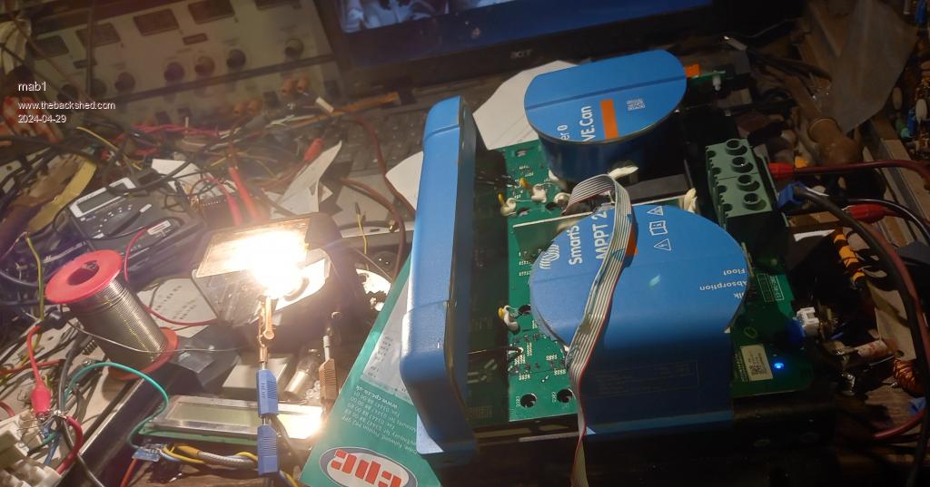 Sorry, the workbench is a bit cluttered  I then spent an hour trying to work out why it wouldn't wake up with 30v or even 60v on its input - then remempered there had been a plug with a link in the 'remote' socket.  Well, bu**er me! It's working  This is the current draw for the 21w lamp with the mppt in standby. 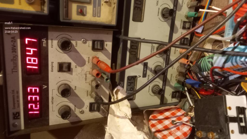 And with a 30v input limited to 1A:  |
||||||
Ok, so now i get to the point of this post:- I've reached the limits of my knowledge on testing- Could anyone advise on how to test the gate drives for the blown fets before i fit replacements? My guess would be to put a resistor (maybe 1K?) Gate to source where the fets will go and scope the voltage? But i don't have any really fast oscilloscopes - the fastest that's currently working is an old valve Telequipment that probably is fast enough (15mhz iirc) but i only have bog standard probes.  I suppose i shouldn't assume the other 4 fets are actually working, but i can probably test that by scoping the inductor? And other advice / tips would be appreciated.  Edited 2024-04-29 08:21 by mab1 |
||||||
An expensive Victron product went dead on it's 2nd birthday... I wonder where I might have heard that before? oh, I know. It was me! the $2,700 3kW 48V Victron inverter I bought. It also died 2 years to the month. I have less than zero interest in helping you with this. I instead will help you build a better, cheaper and very easily repairable mmpt controller if you want. This could become a time sink for you but I wish the best of luck and great help from the high quality EE people here on this forum. |
||||||
You can also add a small capacitor parallel to the 1k as well, like 1nf. You can look in the MOSFETs datasheet for the capacitance. You don't need a fancy scoop, yours will probably do just fine. Watch out while probing you don't short out the drive. I use my scope with an isolation transformer for these things or use differential probes. I would also replace the other MOSFETs, you can't guarantee they are working properly. In this setup you want them to be as close as possible, from the same batch for example. Cool, looks like they are using a separate driver per MOSFET. Also it looks like it's a synchronous buck converter? |
||||||
Well done Mab on getting it apart and going that far. I had two of the 100/50 Victron controllers die. I ended up binning them after seeing that the company potted them. I did not realise that only the inductor potting was holding the cases together. I wish you luck on repairing the controller, those 150/100 controllers are very expensive. I think that here in OZ they are over $1000. Pete |
||||||
I did have the thought that it might be quicker to build one of your mppts than repair this one  , but i only got two sets of boards from you: ones already running with 200v fets; the other has 150v fets installed and is waiting on an inductor - i wonder if it could be pushed to 100A with a suitable inductor? , but i only got two sets of boards from you: ones already running with 200v fets; the other has 150v fets installed and is waiting on an inductor - i wonder if it could be pushed to 100A with a suitable inductor? |
||||||
Thanks for the tips Nick! Those fets are £5 a pop though, so replacing whole batched quickly gets expensive - but pulling them out to test individually would be very time consuming. I'm sort of tempted to test the unit at higher voltage 1st as that might show up other failing fets. Or, as they're 250v 180ish Amp (iirc) fets and there are 11 left, order some of Poidas boards from jlc(?) And just make some proper mppts? Hi pete, yes they really don't want it to come apart: there's a row of caps and two small inductors on the top edge that are potted in too, and those inductors are taped to ally pieces that are screwed to the heatsink - so even after cutting everything you can see, you still have to prize the ally pieces out to separate the pcb from the heatsink! |
||||||
So only 2 years old eh well it should be still under warranty the only reason I went with 2 off 100/50 ones is the 5 year warranty. I did figure getting 5 years for a $300 investment for each of them was a good deal.I did mention to the shop these are prone to die just out of warranty and got told well if yours die 12 months out of warranty they would replace it free of charge. |
||||||
I thought Victron have 5 years warranty. I just ordered a 800vA/48V inverter to hang of my electric rideon mower. ~$400 Jim |
||||||
Well i thought it was 2 years, and i did think this unit might be within that and urged the neighbourto try and get it replaced, but he didn't think that would fly with the vendors. Kind of a moot point: i doubt they will swap it now.  Not had the chance to do much more with in yet. I did try with my little pocket scope as that's good when you want to avoid unwanted earthing of probe gnd and don't have a differential probe. The side with 4 fets does appear to be working; and it appears to operate at about 18 or 19 khz which was lower than i was expecting (i thought they'd run at very high frequency to use smaller inductors). Gate drive for a remaining FET  But the pocket scope appears to have developed an intermittent continuity fault on its input which makes it a bit unreliable for verifying waveforms. |
||||||
Ok, well I've given up on the pocket scope for now and fired up the tektronix 564 this only does 1MHz with the current plugings, but it does do dual trace allowing me to compare waveforms. As this unit seems to run at 16.67kHz (60uS period) it should suffice (don't know why i thought this unit would run at much higher frequency). Here's the comparison of voltage on the two big inductors left and right, showing that both sides are working even though one side is down one highside and one lowside FET:  And here's the gate drives comparison of the left and right lowside FETS (synchronous rectifiers as Nick said):  I put a 910ohms and 2n2 cap gate-source in place of the missing highside FET and compared with one of it's two still working(?) Parallel sisters (NB, due to the alternating scope trigger setting i was using it looks like they're not in sync, but of course they are). The one without the wiggles is the resistor and cap:  Repeat for the lowside FET:  So, as far as i can tell, the gate drives are still working. Sorry my scope pics are not brilliant, but it looks to me like the rise of the gate drives is sharper with the 910ohms and 2n2 than with the FETS. Edited 2024-05-03 07:38 by mab1 |
||||||
Now, i don't know if you looked closely and the scope pic of the inductor voltages, but there's a curious switching feature in the post-freewheel rectifier oscillations 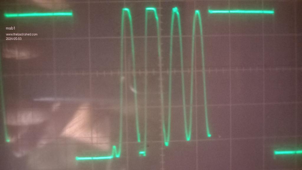 But i wonder if it's to do with an extra pair of smd FETS and a small inductor above the set of six FETS and the big inductor? They're under ally plates that transfer the heat to the main heatsink via the same grey insulator sheet. You can see the ally plate on the left and the soldered connections of the small inductor under the grey sheet thats glued on top:- 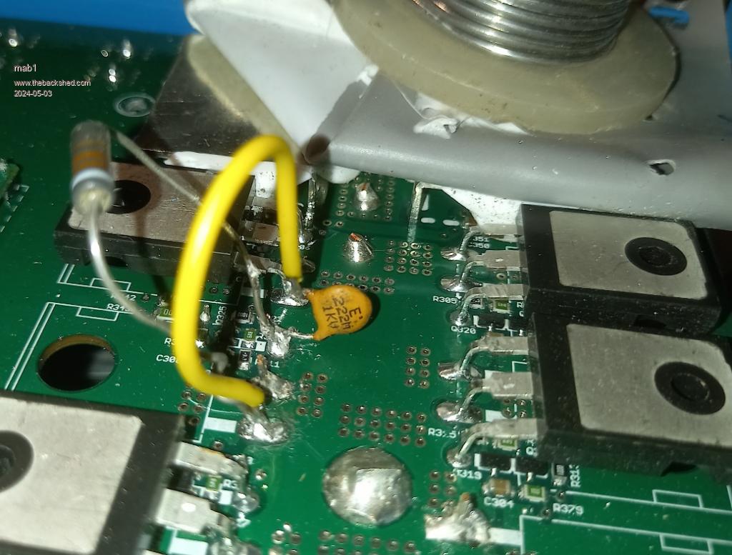 I don't understand why they're there or what they do, which rather limits my ability to understand the waveform or verify that their working . I can only assume that if the left side and right side give identical waveforms, then they probably are doing what they're supposed to do. |
||||||
I don't know if it's worth finding out what the extra FETS and inductors are for, but if someone happens to know or have an idea? But I'm at the point of having to make a decision on the best way forward with this unit: i don't want to waste too much time as there's a high probability that i will ultimately fail, or will get it working only for it to not last very long Option 1 Leave it as it is, two FETS down, fit an external fuse and hope the remaining FETS can handle the current (they're actually rated around 97A continuous), they theoretically would see 100/2 /2 = 25amps. But as it failed when there were six (17.7A each) that seems optimistic. Option 2 As above but take an angle grinder and remove 1/3 of the current feedback shunt resistor on the four FET side, effectively de-rating it. Option 3 Buy two new IRFP4768, hopefully designed to the same spec as original- but they will still be a different batch. Option 4 Buy six IRFP4768 and hope i can swap them without introducing any faults. But at £5 each this is starting to cost money as well as time.  Edited 2024-05-03 08:22 by mab1 |
||||||
A suitable less expensive replacement for those IRFP4768 would be AGM25T16T available form LCSC see Here , and select the least expensive shipping. Cheers Mike |
||||||
Could i take that for a preference for opt 4? Thanks |
||||||
I will go out on a limb and tell you what I see - and that is the low side gate drive is essentially non existent and when it is there it is at the wrong time and for an extremely narrow width. The picture above the comment "So, as far as I can tell, the gate drives are still working "I think tells a story. Looking only at the top trace, the beginning of a highside drive waveform starting in the second grid area is the top FETs on and bottom FETs off, energy into inductor and load. Note the low amplitude only around a volt + & - is due to the drain coupled energy back to the gate, coupling via the D/G capacitance About half way through the 3d grid line area is the bottom FETs body diode conducting as there is no gate drive visible (yet). After the body diode conduction finishes, the waveform starts the decayed ring, after one cycle of ring we finally get a very short period of a gate drive, not sure of your scale 5/10V? it looks to be either a 9V or 18V gate drive - I will go for 9V. The FET drive in the decayed ring is just wrong. There are all sorts of possibilities, one likely one is that the FET drives are determined by a micro controller that is not doing its job properly, maybe due to some collateral damage from the shorted FETs or issues with a sensing circuit component. For low currents/power throughputs the bottom FETs dont need to be switched on to short the body diode for efficiency as there is only low power involved but at higher powers you definitely want the FETs on period to essentially mirror the body diode but there is usually a small caveat. The FETs are switched on just after the body diode starts to conduct and are switched off simultaneously or just prior to the end of current conduction as the energy in the choke can no longer sustain current flow to the output. Looking at the gate drive picture again, you see a very narrow pulse long after the body diode conduction period and during the normally decayed ring period. Also interesting is that the high side FET also appears to turn on again briefly immediately after the bottom gate drive is turned off, however no upper gate drive is evident from the picture above the lower narrow gate pulses to explain this. It is possible that during the narrow on period some energy is put back into the inductor from the output capacitors and released through the top trace flat area as the top FETs body diode conduction returns that energy back to the input + rail. A bit like an unintended boost converter cycle. Hope this helps - just be aware that for low powers maybe a very narrow gate on period like that is ok or normal (but not WHERE yours are showing), many high powered synchronous buck converters dont bother with FET drives below a defined output power as the gate drives energy required is often around the same as what is recovered due to the increase in efficiency and it is more difficult to determine small changes in current for lower powers so they often only drive the synchronous FETs when there are decent current levels to detect when to turn the FETs on and off. Last comment maybe this is just an acceptable quirk of their design and under much higher power throughputs all these waveforms start to behave normally, but its not how I would leave a design to go into production. MAB - I hope the CRO fairy visits you one night and leaves a nice present.... Edited 2024-05-03 10:49 by wiseguy |
||||||
Hi wiseguy, thanks for you thoughts. After i posted it did occur to me that the lowside gate pulses didn't show up where expected, but as you say I'm running at very low power so far. But also i was thinking it may be something to do with the additional smd FETS under the ally plates - i can't reach their gates to see what they're doing. I've done a pencil sketch of what i think the circuit might be: the upper drawing is sort of the typical syncronous dcdc converter i was expecting, the lower is what it looks like - as far as i can see without dismantling (and makes no sense to me):-  I did notice when the mppt was hunting up and down, the narrow switching event in the ringing would widen as the main switching even on the left narrowed (moving to higher input voltage), and visa versa. Maybe if i try running it at higher power it'll look more reasonable? i could also check if the remaining 4 FETS warm up evenly (all working) or some remain cold (not working). TBH my lack of understanding of the circuit tempts me to options 1 or 2 as it's quick and doesn't cost anything. re scopes: yes i ought to buy a good modern one for faultfinding, it can be a bit frustrating testing faulty electronics with flaky scopes. But to be fair the valve scopes usually work ok - once they've been on for a couple of hours |
||||||
I didnt answer your options. I think leave it as it is & more testing at higher power levels and higher input voltages are required to see if the waveforms become more "normal", with a few more amps out. So I am leaning for option 1 to start with and to try to obtain proper waveforms and if that happens, now add option 3! I would hope to see a gate drive that starts as soon as the upper FETs turn off and disappear just before the ringing starts, it would also be nice if they stayed gone for the entire ringing period. The schematic you have drawn I can't really make sense of, I expected it to be just 2 x independent paralleled buck converters with their output chokes summed. In my experience of working with FETs If there are more than 1 in Parallel and a FET or FETs are shorted, they usually "took one for the team" and the others are probably fine. If I was launching a satellite or relying on electronic braking for something really really important, I might possibly replace all FETs to be sure to be sure, but in my vast experience of fixing many hundreds of paralleled FET failures and isolating and fully testing remaining good FETs, I only check static readings now and if the remaining FETs appear to be working fine just replace the damaged ones. Others may have different experience or different philosophy - that's also fine. Oh & the FETs Mike suggested, I would quite happily put them as replacements for just the faulty ones, their specs look quite well matched - again I would not go into production with assorted FETs but it is a lowish cost experimental repair job. Edit: Holy crap I just noticed this is my 1,000th post..... Edited 2024-05-03 12:42 by wiseguy |
||||||
Thanks again Wiseguy, some higher power and higher voltage testing will be done, and i'll post what i find (and review my options). I'm pushing ahead with my 2nd Poida MPPT as it's probably quicker to get my neighbour up and running with that, then i can play with the Victron with more leisure, and not blow it up unnecessarily. Very interesting to hear you experience on not replacing parallel FETs that pass a static test, and on mixing FETs - if i can get some of those that Mike linked (not sure they sell to the UK, and those FETs didn't appear on my usual suppliers list), then I'll probably get some - although two IRFP4768's from my usual supplier won't break the bank.1000 posts!  i'm a long way behind you. i'm a long way behind you. |
||||||
| Page 1 of 2 |
||||||


