Menu
JAQForum Ver 19.10.27

Forum Index : Electronics : Trying to repair a Victron MPPT  controller

   Page 2 of 2    
Posted: 03:54pm
04 May 2024
Copy link to clipboard
mab1
Senior Member

It's a bit thrown together (with whatever caps i could find), but the Poida MPPT is up and running for the neighbour   and the battery is charging.
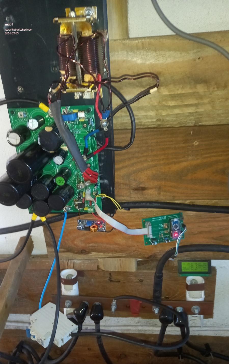


I'm still impressed with this design: it just works! I started with one panel, and a 32A breaker. Then 2 panels with a 60A megafuse. Power is waning as the sun's heading west. I could go up to 3 panels but that would give an OC voltage of about 120V, and as the connections are open plan that might be a little risky. This aerosharp based inductor should be good up to 100A, based on my saturation tests, but i don't know how hot it will get yet...


There seems to be an issue with the input current calibration (sorry if the display layout is unfamiliar - i rearrange it to suit my VFD displays,  and added a energy today figure).  


But the output current and voltage are about right. One of the temp figures is wrong too - turns out that salvaged temp sensor isn't a 10k ntc.  
Edited 2024-05-05 01:58 by mab1
 
Posted: 07:49am
05 May 2024
Copy link to clipboard
nickskethisniks
Guru

Try using the best diodes you have, this will be the weakest link of the system. With this input/voltage ratio. Also using 40khz vs 20khz will half the ripple current.
Did you follow Dex his thread? Make sure if the controller (especially the MOSFET) fails the battery can't be over charged.


If I design a new controller board, it could be beneficial to include a contact or relay for fault detection.
Edited 2024-05-05 17:53 by nickskethisniks
 
Posted: 01:10pm
06 May 2024
Copy link to clipboard
mab1
Senior Member

Thanks Nick, good point about failsafe - on my own system i have a.c. coupled solar and diversion controllers on the battery so the failure of a mppt controller would be covered by the existing dump loads.

I'm not sure i remember dexs thread but will have a look...

In the meantime i did try higher power on the bench, but was struggling to get above 100w, and the MPPT was still operating in discontinuous mode with its inexplicable syncronous rectifier gate pulse:


So i bit the bullet and put it back on the neighbours system (starting with a single panel), just to see how it would handle higher powers.  As i wanted to probe it i left the heatsink off so i didn't want to push it too hard   .

I didn't lug the valve scope over there so had to make do with the pocket scope which seems to be behaving at the mo, but being single trace doesn't allow comparison of inductor and gate drive waveforms.

It started up and went up to about 22A output.  And the lowside gate drive looked like this:


Inductor voltage with two panels in series ((about 29A):


And the lowside gate drive:


So it does look like the syncronous rectification does work once its in continuous mode  

After several minutes of running at around 25 - 30A with no heatsink the only devices that felt warm were the two lowside fets on the blown fet side, and they were barely warm; the three lowside fets were probably warmer than the highside fets but it was hard to feel the difference. Both sides showed about 14mV across the shunt resistor.


So I've ordered some new fets (IRFP4768 might as well have the same type).
Edited 2024-05-06 23:12 by mab1
 
Posted: 05:12pm
07 May 2024
Copy link to clipboard
mab1
Senior Member

I've read through -Dex-s thread - gives me some food for thought - particularly as i was considering building myself a 250v version of poidas MPPT - i maybe should be looking at SiC diodes (although the Vf may be higher, but options above 200v may be limited anyway).
 
Posted: 02:54pm
10 May 2024
Copy link to clipboard
mab1
Senior Member

Update:
Well the new parts turned up and were installed . Tested fine on the bench  

Reassembled on the heatsink and whats left of the cover, and tested again - all fine  

Reinstalled at the neighbours with only 4 of the 6 panels, all fine, 60A into the battery and still cool, tapers off as it should going into absorb mode  

Leave it going and pop back late afternoon just to be sure-

It's dead!  

It isn't shorting the pv array this time,  and it's drawing 1/4A from the battery, so it's something different this time.

Put Poidas mppt back into play and return with the victron. At least it comes apart easily now..  

The FETS all diode test fine and the fuses aren't blown, but there's no response to 12v being applied but that 0.25A draw...

The 12v supply is pulling the current but i guess it current limits at 1/4A and the output is only 5v. Find that the 5v(?) reg on the 'brainboard' is getting hot, and it's output is only 1.2v, and after some more voltage testing it looks as though the microcontroller itself is shorted  

If i were more paranoid i might suppose it had a deliberate self destruct mode if it detects it's been repaired, but a more rational possibility is that the fine metallic swarf created when i cut my way in managed to short out something on the logic and killed it; i did try and remove as much as i could, but there's always a risk that brushing and blowing could force some of the fine stuff into small spaces between smd legs etc.

Feeling a little hacked off at the mo.'  

If anyone has any ideas at this point I'd like to know,  but I'm thinking it's game over.

Still, there are lots of goodies in there that could be re-purposed in home made MPPTs
Edited 2024-05-11 00:57 by mab1
 
Posted: 03:35pm
10 May 2024
Copy link to clipboard
wiseguy
Guru


That sure sucks! I was given a written off "unrepairable" laptop about 2 years ago, that was fixed within an hour or so and still runs a treat.  Offered it back but they had replaced it and told me keep it with their blessing.

It had a short on the 5V line that fed everything everywhere and had about 50 bypass capacitors on its paths around the PCB.
I tracked (unintended pun) it down to 3 capacitors in close proximity to each other and when I lifted the second one the short disappeared and the laptop worked fine again. (3c fix if you don't count the hour) - I looked at it as an hour of entertainment.

Moral just maybe there is something similar happening to the Victron controller - of course if it has an RTC on board pre programmed for 24months + 1 day maybe you cant outsmart it.....
Edited 2024-05-11 01:35 by wiseguy
 
Posted: 08:28pm
10 May 2024
Copy link to clipboard
mab1
Senior Member

That's certainly work a look - i tend not to think of caps going short. But I'm not too optimistic and don't want to spend too much time now that it feels like a lost cause. Maybe it can sit on the shelf for a while til i feel like playing with it- perhaps when the tax return needs doing and i want a diversion  
 
Posted: 01:31am
12 May 2024
Copy link to clipboard
Godoh
Guru

Sorry to hear of your troubles. I had two Victron controllers blow up. I tried to pry them apart and gave up. My take was that they were just not worth trying to repair.
You have done an amazing job getting that far with dismantling the one your fixing.
Pity that it blew up again after so short a time
Good luck with it
Pete
 
Posted: 01:34am
12 May 2024
Copy link to clipboard
Godoh
Guru

I agree with your first idea of reducing the voltage into the regulator.
I don't know why people want to run such high voltage DC around their place.
I don't know about UK but in Oz the maximum voltage a non electrician can work with is 120 volts DC.
I just connect my panels in 2 series groups and parallel the groups. 75 to 90 volts DC is plenty enough if thing so pear shaped.
Pete
 
Posted: 11:04pm
13 May 2024
Copy link to clipboard
mab1
Senior Member

Hi Pete,

Yes it made no sense to run the panels 6 in series when they were literally a few yards from the controller - i think he followed bad advice from the seller   . Current plan is to run 2 x 3 series or 3 x 2 series depending on which controllers he ends up with (he's not buying Victron this time), and longer term he's planning on getting a 24 or 48v inverter (the latter if he listens to me).
 
Posted: 01:04am
14 May 2024
Copy link to clipboard
Godoh
Guru

Hi Mab, I don't know about UK but here it is possible to by either Blue Sky controllers or PowerMR controllers for around $120 each.
I have 4 PowerMR controllers , 60 amp
They seem to work fine.
He could buy two PowerMR controllers and then split his panels into two groups. The work fine with the outputs paralleled.
Just don't parallel the inputs.
Pete
 
   Page 2 of 2    


To reply to this topic, you need to log in.

© JAQ Software 2024