|
|
|
 |
|
|
Building my CNC Router
|
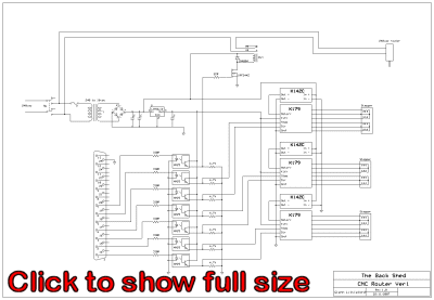
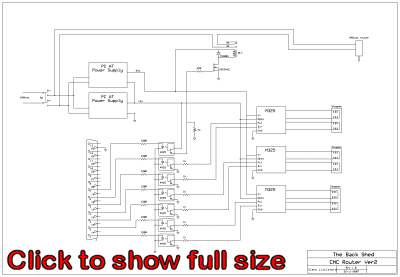
NEVER plug or unplug the parallel port while either the PC or CNC table interface circuits are powered up. Always make sure the PC and CNC electronics are tuned off when you plug or unplug the parallel port, or you will damage your computer. Trust me, I've seen it happen several times, once in a laptop that needed to have the mainboard replaced as a result, very expensive. Below is the first circuit I put together for my CNC router. The opto couplers are there to protect my Printer Port, see above. The relay is used to switch the router head off and on, and uses a simple MOSFET driver circuit. The MOSFET shown was pulled from a dead computer UPS, UPS's, like most PC hardware, are great for spare parts. At first I used K179 and then KT-5191 stepper drivers ( see next page ), these stepper controllers need a logic high to switch, and this is supplied by the opto isolator outputs. Later I moved to a microstepper controller for my stepper motors, and these needed a sink input to switch, ie the input needed to be switched to ground, so I had to redesign the opto driver part of the circuit. More information on the microsteppers is on the next page. To add in the near future....
|
|
|


