Newbie
Joined: 02/02/2016
Location: United KingdomPosts: 23
| Posted: 07:07pm 20 Jun 2018 |
Hi,
I use a test set by N7ZWY for evaluating motional parameters of crystals, combined with an oscilloscope. It works great but ties the scope up, requires several manual measurements and need to write them down somewhere so it is time consuming.
For a while now I have been thinking of ways to automate this and have the possibility of storing the results on an SD card for later use and this is where the MM fits in.
The procedure involves taking few voltage and frequency readings. Now I am OK with measuring voltages but am struggling to understand how to do frequency measurement with the MM. The manual says that COUNT function does that but is limited to 300kHz. The crystals I measure go up-to 27MHz so not sure how to make the MM measure that. I would prefer to avoid using a pre scaled.
Is this feasible and if so any starting help anyone please?
Kind Regards
Elia Mady
M0ZHN
Newbie
Joined: 02/02/2016
Location: United KingdomPosts: 23
| Posted: 07:28pm 20 Jun 2018 |
I have been thinking some more and wonder if using two timers would work. One of them using interrupts, although not sure how. Is this better using an fFunction?
Guru
Joined: 06/06/2011
Location: AustraliaPosts: 3281
| Posted: 09:29pm 20 Jun 2018 |
Measuring 27MHz on the Micromite is not feasible (for many reasons). Off the top of my head the best way that I can think of is to build a frequency counter using discrete chips then read their value.
Guru
Joined: 11/12/2012
Location: United KingdomPosts: 10180
| Posted: 09:57pm 20 Jun 2018 |
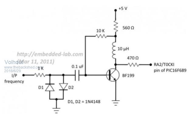
I think this is possible by using the frequency as input to one of the PIC's timers and then reading the timer at intervals. I believe it could be done with a CFunction. Of course you will need a trivial circuit to convert the crystal output to a TTL signal as input to the timer

Guru
Joined: 09/11/2017
Location: AustraliaPosts: 446
| Posted: 11:14pm 20 Jun 2018 |
This might not be exactly what you are after but maybe will spark ideas.
Silicon Chip published a 6GHz+ Touchscreen Frequency Counter which was an add on module for the Micromite Plus Explorer 100 in the Oct/Nov/Dec 2017 issues. Since it is on the MM Plus and the basic programs are supplied you can change it and add other functionality to suit your purpose.
Newbie
Joined: 02/02/2016
Location: United KingdomPosts: 23
| Posted: 05:07pm 21 Jun 2018 |
Geoff, Mather,
Thank you for the replies. As per Geoff's idea I did some searches on Google and found this:
https://www.swharden.com/wp/2016-09-05-vhf-frequency-counter-with-pc-interface/
It looks promising, I will have a go at porting the simple python code to MMBasic.
Azure, thanks, will have a look at the magazine article. Maybe that will be an option too.
Kind Regards,
Elia, M0ZHN

Senior Member
Joined: 18/03/2012
Location: FrancePosts: 155
| Posted: 12:39pm 22 Jun 2018 |
Hi Elia,
you can try on a test board two (or 3) 74LS90 (divide by 10) with your xtal oscillator
with /100 (or /1000), you got a range of 300 KHz maxi
it is ok to count with a MicroMite
73s from F1FCO
Pierre, from Nimes, south of France
73s de F1FCO
Guru
Joined: 07/09/2016
Location: United KingdomPosts: 2170
| Posted: 08:39pm 22 Jun 2018 |
I built a Frequency meter with a USB serial interface on an old euro card.
I wanted it absolutley perfect to whole Hz and used a "gold" TCXO at 12.288MHz 100ppb as the reference XTAL and divided it down to give a very precise 1 second gate into that same 8154.
It was more involved than that one above because I divided down using discrete counter chips (4017s !), I didn't want to rely on a processor clock for the gate, but it is incredibly accurate and good from 0Hz to about 70MHz in 1Hz increments
I have a small vid of it working here. https://www.youtube.com/watch?v=pakCeRi2fJQ&t=97s
If you are interetsed, I can bundle the circuit schematics in Eagle and post them. It was originally powered by a PIC16F877 but was the subject of a brain transplant to a 44pin micromite. It has given sterling service and is a daily driver for me.
I intend to put a frequency generator in the same case... one day... just need to get round to it.
Guru
Joined: 09/08/2007
Location: AustraliaPosts: 4406
| Posted: 03:26am 23 Jun 2018 |
You can always divide the frequency right down to something manageable and measure that as already suggested.
If you divide it down far enough, its even possible to measure the period. Accuracy and resolution should not be a problem, but its going to be a slow measurement.
Cheers, �Tony.

Guru
Joined: 20/06/2011
Location: AustraliaPosts: 2947
| Posted: 06:55am 23 Jun 2018 |
The only problem with dividing is you lose resolution.
ie. a divide by 10,
You could be as much as 9 counts out, as the source has to change states 10 times before the output changes once.
Regards,
Mick
Mick's uMite Stuff can be found >>> HERE (Kindly hosted by Dontronics) <<<
Guru
Joined: 09/08/2007
Location: AustraliaPosts: 4406
| Posted: 07:07am 23 Jun 2018 |
Not if you increase the measurement interval by the same proportion.
If you have 1Mhz and you count over one second, you will have a one million count, with 1Hz resolution, but with a one count uncertainty.
If you have 10Mhz, first divide that by ten down to 1Mhz, and then count over ten seconds and you will have a ten million count and get the same 1Hz resolution with the same one count uncertainty.
The measurement just takes ten times longer to do, but accuracy and resolution remain the same.
If you are stuck with a slow hardware/software and you wish to measure up to very high frequencies with good resolution, you can still do it, but the trade off is time required to make the measurement.
Cheers, �Tony.
Guru
Joined: 20/06/2011
Location: AustraliaPosts: 2947
| Posted: 09:50am 23 Jun 2018 |
@Tony,
Yes, you are correct, I didn�t consider that option.. but can be excessive if it is divide by 100 or 1000..
Regards,
Mick
Mick's uMite Stuff can be found >>> HERE (Kindly hosted by Dontronics) <<<
Guru
Joined: 21/01/2012
Location: AustraliaPosts: 689
| Posted: 01:11pm 23 Jun 2018 |
Just an idea -
Use the signal frequency to drive the pic32mx itself. Run a simple incrementing counter, and gate it using the 1 pps from a gps. At the end of the gate, print the counter and reset it, and wait for the next gate start.
Guru
Joined: 05/03/2018
Location: NetherlandsPosts: 5021
| Posted: 11:45am 25 Jun 2018 |
IF the MX has a counter input, it should be possible to simply let it increment on every edge, and frequently read out the counter.
With a 16 bit counter you could do this in 1msec period, and count up to 60MHz.
There are HW limitations to the frequency you can input to the counter, but this can hardly be an issue with a 50MHz+ chip like the PIC32 series.
I build a 50MHz frequency counter this way in a 4MHz PIC16F84 20 years ago.
For frequencies above 40-50MHz, you would need a prescaler (not a 74LS90....your MX is far faster than the separate TTL chips).
You probably could have use of a Cfunction, but I bet you can do it in MMbasic also.
The 1msec reading of the counter register does not need to be accurate, as long as you have an accurate time as a reference.
The 1msec loop is only needed if you have a 16 bit counter. If your HW has a 32 bit counter, you simple read it every second, and divide by the reference time.
something like
main loop
get reference time
clear work register (32 bit)
1msec loop (i.e. 1000 times)
read counter
add to work register
end loop
get current time
subtract reference time = delta time
divide work register by delta time = accurate frequency
end main loop
This you can do in MMbasic, I am sure...
PicomiteVGA PETSCII ROBOTS
Guru
Joined: 09/08/2007
Location: AustraliaPosts: 4406
| Posted: 02:32am 26 Jun 2018 |
You can also use the 1mS counter overflow to trigger an interrupt, and count up the interrupts over whatever time period you need to get the required final resolution.
Cheers, �Tony.
Newbie
Joined: 02/02/2016
Location: United KingdomPosts: 23
| Posted: 03:46pm 27 Jun 2018 |
Thank you everyone for the many responses and suggestions, there is a lot there to think about. I will try using a divide by 10 or 100 prescaler first and see how that goes. This is within my programming capabilities, just....
I also want to try Scott Harden's counter that he did with a Raspberry Pi, not sure if I have the skills to port his software but will try.
Will post about my experiments when I get to them, work is getting in the way 🙁
Kind Regards,
Elia
Guru
Joined: 05/03/2018
Location: NetherlandsPosts: 5021
| Posted: 11:25am 29 Jun 2018 |
In my previous post I suggested to use an internal timer clocked by the 27MHz frequency. That suggestion was premature, and incorrect (the architecture of MMbasic on the PIC does not allow that, thanks Geoff for reminding).
I have to agree with others that na external divider is the solution.
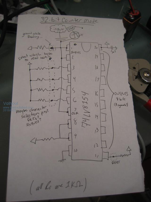
A simple solution is to use the SN74LV8154-EP
It has 2 internal 16 bit counters that can be chained to a 32 bit counter.
The output is 8 bit parallel with 4 select inputs. So you can read out all 32 bits in 4 bytes.
You only need to provide an accurate count gate (i.e. a 1msec pulse) and clear the counter before opening the count gate.
The frequency guaranteed over the wide temp range (-55...+125C) is 25Mhz, so I expect if you keep it at room temperature, it will work fine for 27MHz. It is 3.3V in so you may want to add a small amplifier before it to easily tap into oscillator circuits.
Good luck building....
Volhout
PicomiteVGA PETSCII ROBOTS
Guru
Joined: 11/12/2012
Location: United KingdomPosts: 10180
| Posted: 02:15pm 10 Jul 2018 |
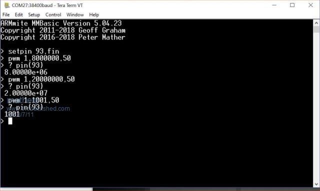
The latest version of the Armmite code includes support for a high speed frequency counter.
Using SETPIN 93,FIN or SETPIN 93,CIN, pin 93 (PG8) is configured to clock a timer as suggested in the posts above. The timer then generates an interrupt on timer-overflow (16-bits) allowing total counts up to 2^63 before counter overflow (normal Micromite integer).
I've tested the functionality up to 20MHz which is the fastest the PWM on the Armmite will run and it seems to work perfectly.
The concept could be engineered into the firmware of the MM+ and/or MMX but the PIC has far fewer timers than the STM32 so it may compromise other functionality. There is no chance of doing it on the MM2
Senior Member
Joined: 18/03/2014
Location: AustriaPosts: 133
| Posted: 08:37am 11 Jul 2018 |
@matherp
SUPER, i have a Board, but no time for tests !
Wolfgang