Guru
Joined: 02/02/2017
Location: AustraliaPosts: 1432
| Posted: 04:46am 05 Jul 2022 |
I think you better have a copy of the firmware that operates as a variac.
The SPWM amplitude is controlled by a pot. I think it soft starts up to the pot setting and there it remains. You can then immediately command a change in AC voltage via the pot.
No closed loop control.
pot setting = PWM duty width
This code was fun to play with. I always found I could make the toroid growl
with sudden increases in AC output via twisting the pot. Slow changes to increase voltage made far quieter grunt. Always there was no grunt when reducing AC voltage
by twisting the pot the other way. Fast or slow reductions were quiet.
From this play, I found that the grunt sounds were proportional to rate of increase of output voltage WHEN NEAR SATURATION. IF the AC voltage was only 1/2 max. or maybe 120V no grunt even with fast increases that stop at levels below the start of saturation. This is from testing years ago so my memory will not be great.
I can only relate experience with Aerosharp 1.5kW and 3kW toroids
that use the factory wound 240V secondary winding and my roughly wound primary.
At 240V AC RMS output on the secondary, there is some but not a lot of evidence
of a saturating core. It goes like
100V - none
200V - none
220V - a tiny bit
240V - a small bit (a slight hum at steady state)
250V - 2x that (clearly a hum now)
260V - 4x or more as at 240V (good and solid hum from the toriod)
Something like that.
Saturation was detected by me from observing primary current peaks.
So at 220V AC I could just see the small current peaks at AC output
zero crossings.
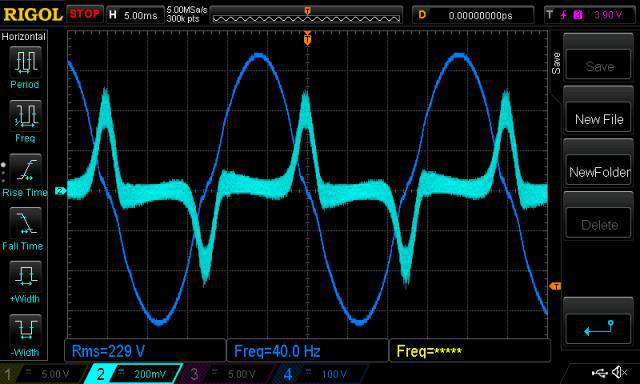
here is current and AC voltage output at 40Hz and 240V AC output
This is an extreme example.
The toroid core/secondary winding is not designed for this combination
since it clearly is saturating.
It's not going to blow up or burn out it will just be inefficient.

The earlier code (when changing from "stop" to "run") will terminate the soft stop
ramp down and reset the code to initial conditions required for a soft start and then start ramping up. The ramp position is set to zero when initialised.
This code execution will occur at the time the run/stop signal is checked
and this check happens at 100Hz, every zero crossing.
Think of it as a clock, ticking at 20kHz, making a PWM pulse.
This is the only interrupt and so it is never interrupted by other code.
It always will be executed, with very little time jitter (+/- a few ns)
and make a pulse.
In the spare time after the interrupt has completed which is about 80%
of cpu time, the code can do what else is needed such as
respond to a zero crossing.
The zero crossing event triggers the PID closed loop code to run as well as
the checking of the run/stop signal.