Guru
Joined: 08/02/2015
Location: New ZealandPosts: 1162
| Posted: 08:56am 27 May 2020 |
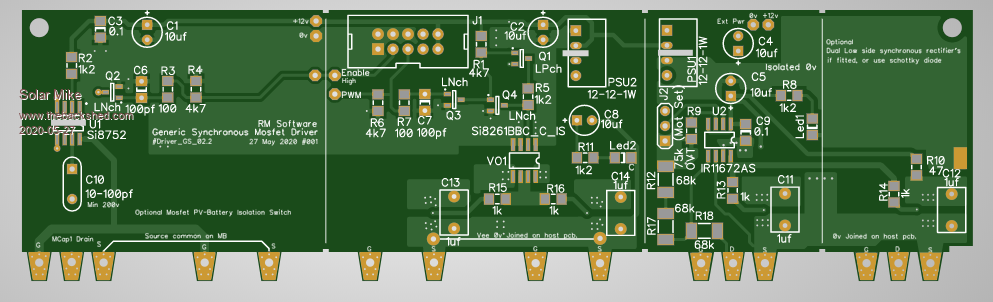
Made changes to the generic driver module to allow it to run with > 200 volts input, the synchronous rectifier driver chip IR11672 has a max sense input of 200v, have added a resistive divider to allow in excess of 250v; this change also affects the chip voltage sensing points, but seems ok looking at the spec sheet.
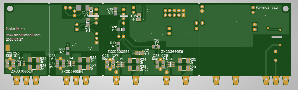
As these drivers have limited current drive of only 2 amps, have implemented supplementary boosters for each mosfet using the ZXGD3005.
Have made the pcb so unwanted optional sections can be simply cut off, rather than designing multiple boards, the cut off bits can also be used standalone. Noting that all mosfets are mounted spaced 28mm apart on the heat sink.
Will make a schematic to check it.
Cheers
Mike
Edited 2020-05-27 19:06 by Solar Mike