Guru
Joined: 02/02/2017
Location: AustraliaPosts: 1432
| Posted: 06:39am 25 Dec 2020 |
(whoops, hit post before anything)
Previous work with inverters has used one Arduino Nano to produce the
PWM signal that is then sent to 1/2 bridge driver ICs that then make the low and high side gate drive outputs with deadtime.
A 240V AC inverter needs 2 of the half bridge drivers and MOSFETS to produce
the sinewave output.
I have been playing with 3 phase AC and I found all I need is
an Arduino Mega to give me the 3 PWM outputs. The Mega has a lot of timers
suitable for the job and I use timer no. 1, 3 and 5.
It is simple to generate the 3 SPWM (sinewave pulse width modulation)
and to have them output 120 degrees phase difference to each other.
There are already ICs that do this, the EG8030 but you and I know it's
far more fun to do it yourself. And you get to control everything about the inverter
behaviour.
I have a couple of videos of this:
first is showing the SPWM of the 3 outputs from the single Mega.
I low pass filter the PWM to give a voltage so that it can be captured by the DSO
I alter the frequency from 20 Hz down to zero then reverse direction and go to -20Hz
Reverse direction Ā= negative frequency for this project.
https://youtu.be/Xy5Er08NyLg
and here is a video of the AC servo motor rotating. Speed and direction controlled by
a pot.
https://youtu.be/aqoJkCixJag
There is not a lot to this. The breadboard is not ideal for 20KHz PWM but it works.
I even made some code that takes the position sensor output from motor and ran it
in position control, with closed loop feedback of position error driving the motor.
The position encoder outputs 5V logic level quadrature signals which are easy to detect and accumulate counts.
Aaron here is interested in a 3 phase inverter.
I suspect he will build it with 3 similar toroids, with the AC outputs having one of the wires all tied together to make a Neutral, and P1, P2 and P3 outputs all at 240V AC 50Hz.
I think I can do the firmware for this.
Aaron wants some process control:
- soft start and soft stop from zero to 240V 50Hz
- reduce frequency when input voltage drops, in an attempt to lower the motor power draw.
- Āuse the inverter to power a 3 phase water pump, driven by a standalone solar array, maybe with or without batteries.
Already you can do this, just buy a cheap Chinese VFD.
But we need to complicate our lives, to be spending lots of time developing projects.
If we just go the easy and fast way, there will be far too much time left for us to
work in the garden, paint the house or go to church on Sundays.
I know what I prefer.
To get an idea how simple it is to get a 3 phase output see the code I used for the videos:
#define NPWM Ā360
#define PPWM 800 Ā Ā Ā// 800 = 20kHz PWM
uint16_t p1count,p2count,p3count;
int pm;
float fpm;
uint16_t l[NPWM];
int _v;
void setup()
Ā{
Āint i;
Āfloat f;
Ā// _v is used to reduce the amplitude of the SPWM.
Ā// I have code that takes a current sensor output on DC supply
Ā// and reduces amplitude to maintain a maximum current setpoint.
Ā// the AC servo motors have an inverse relationship of
Ā// current to RPM
Ā_v = 250; Ā Ā// for now, maximum current or amplitude.
Āfor(i=0; i < NPWM; i++)
Ā Ā{
Ā Āf = 2.0 * 3.14159 * (float)i/(float)NPWM;
Ā Āf = 0.8*(float)PPWM * (1.0 + 1.0*sin(f)) * 0.5;
Ā Āl[i] = (int)(f); Ā
Ā Ā}
Āt135();
Ādo_phase(0);
ĀSerial.begin(115200);
Āpm=0;
Āfpm = 0.0;
Ā}
void t135()
Ā{
// set up the 3 timers
ĀpinMode(46,OUTPUT);
ĀpinMode(5,OUTPUT);
ĀpinMode(11,OUTPUT);
ĀTCCR1A = TCCR3A = TCCR5A = _BV(COM5A1) | Ā_BV(COM5B1) | _BV(WGM51);
ĀTCCR1B = TCCR3B = TCCR5B = _BV(WGM53) | _BV(WGM52) | _BV(CS50);
ĀOCR1A = OCR3A = OCR5A = 1;
ĀICR1 = ICR3 = ICR5 = PPWM;
ĀTIMSK1 |= (1 << TOIE5);
ĀTIMSK3 |= (1 << TOIE5);
ĀTIMSK5 |= (1 << TOIE5);
Ā}
ISR(TIMER3_OVF_vect) Ā Ā Ā Ā
Ā{
// each timer needs the new PWM width every 1/20,000 second
Ālong c;
Āc = ((long)l[p2count] * (long) _v) >> 8;
ĀOCR3A = c;
Ā}
Ā
ISR(TIMER1_OVF_vect) Ā Ā Ā Ā
Ā{
Ālong c;
Āc = ((long)l[p1count] * (long) _v) >> 8;
ĀOCR1A = c;
Ā}
ISR(TIMER5_OVF_vect) Ā Ā Ā Ā
Ā{
Ālong c;
Āc = ((long)l[p3count] * (long) _v) >> 8;
ĀOCR5A = c;
Ā}
void do_phase(int pc)
{
Ā// have counters pointing at 3 positions in the 360 deg sinwave
Ā// clock them forward or back at the speed obtained from the pot
Ā// on A0
Āp1count = pc;
Āp2count = pc + 120;
Āif (p2count >= 360) Ā Āp2count = p2count - 360;
Āp3count = pc + 240;
Āif (p3count >= 360) Ā Āp3count = p3count - 360; Ā
}
void loop()
{
int p,i,cmax;
float v;
// read pot on A0 for phase increment or velocity
p = analogRead(0);
v = Ā(float)(p - 512)/100.0;
// update phase with phase increment from pot on A0
fpm += v;
if (fpm >= 360.0)
Āfpm -= 360.0;
if (fpm < 0.0)
Āfpm += 360.0; Ā
pm = (int)fpm;
do_phase(pm);
}
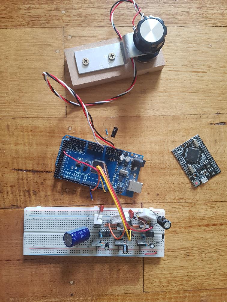
here is the test setup, with the new type Mega board at the right for size comparison.
These boards cost $18 from ebay, probably 1/3 that from aliexpress
and the 3 half bridge MOSFET drives. I use IR2004 1/2 bridge drivers since I had them here already. Each 1/2 bridge has a low side MOSFET and a high side MOSFET.
The high side FETs need the diode/cap charge pump.
When running this with about 1.5 Amps at 25V into the AC servo motor the MOSFETS
remain at room temperature. That is a sign of fast switching.
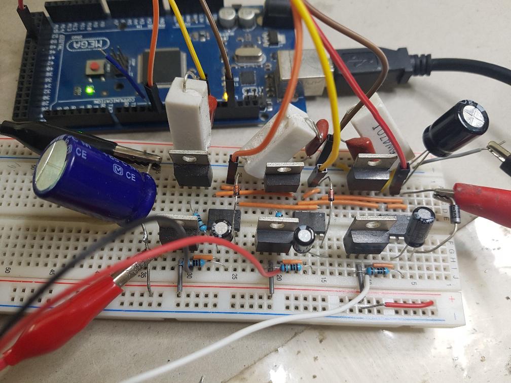
There are 3 x RC snubbers on the low side. They help a bit to reduce
problems from doing this on a breadboard.
Motor DC supply on the left. 12V IR2004 IC supply on the right.
Edited 2020-12-25 16:59 by poida