Guru
Joined: 02/02/2017
Location: AustraliaPosts: 1432
| Posted: 11:05am 28 Dec 2020 |
renewableMark:
that motor seems ideal for testing.
I Think I would like that motor very much.
..
..
In other news I have spent a couple of hours calibrating the
Tektronix A6902B Isolator.
What is that?
It gives you 2 channels of isolated inputs. Each input may be +/- 500V from ground.
You can connect the ground lead clips to any voltage +/- 500V and see the voltage
on the tip relative to their ground clip.
(All CROs and DSOs have the ground leads connected to each other and this is connected to mains Neutral and Earth. Isolated inputs are a good thing with power electronics)
That, plus the Pirtek DP-25 isolated differential probe will let me probe
all 3 phases with any ground reference for any of the 3 phases.
I plan to have individual AC output voltage control for all 3 phases.
Not just one phase as the inverters we have built so far.
So I need to measure all 3 phase's voltages, all referenced to the neutral,
which will probably NOT be close to DC supply ground.
Even if it was, I will want to assume it is not and be able to accommodate this.
When I got the A6902B channel 2 was about 20% out in gain on channel 2. That is a lot. It was time to follow the Tek service manual instructions and calibrate it.
Now I have this:
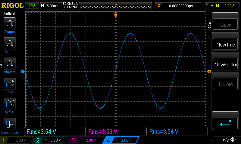
where Light Blue is the Pirtek,
Purple and Dark Blue are the 2 channels of the A6902B
Input signal is 10V p/p sine wave 50Hz.
This is 3.53V AC RMS
They all are very close.
Undoubtedly the 3 phase inverter will have unbalanced loads and unbalanced outputs
and I want to be able to see this to a few % or better.
here they are with mains AC voltage:
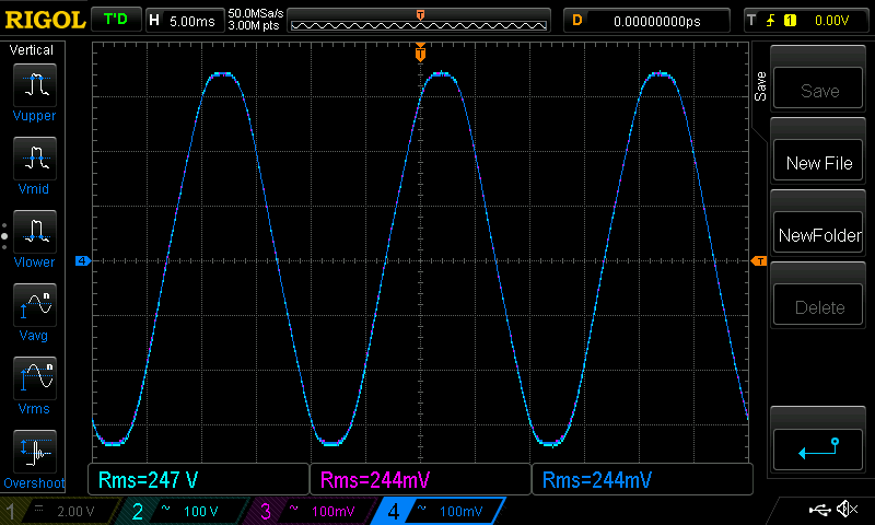
there is a bit of a difference now. I could have calibrated them with mains voltage
as input but that is a dangerous thing for me to do.
Calibration changed when I change from 2V/div to 100V/div. Oh well.
They are now all close enough so that's that.
Now, the transformer.
I think I will make one using 3 toroids. I have 4 on hand, and they may not be all identical.
With individual voltage feedback control for all 3, I think it will not matter
much that the toroids are different. The feedback control will automatically
handle any differences in output voltages for each phase.
The prototype will only need to produce about 1kW per phase and probably less.
This is 4 Amps at 240V per phase.
So I intend to wire the primary in delta and the secondary in wye plus a neutral.
I will need 3 240V->12V step down transformers for voltage feedback.
I can use a single phase full bridge inverter which gives me 2 phases.
And use another single phase full bridge inverter but only use 1/2 of it.
There are a couple of spare boards here so that's sorted.
What has to be built is the 3 phase controller board with 3x IR2148 drivers and charge pump bits, probably on perfboard.
Time for a few days off in the bush chasing birds with my camera for now.
See you all next week.