Guru
Joined: 08/02/2015
Location: New ZealandPosts: 1162
| Posted: 12:10pm 01 Feb 2021 |
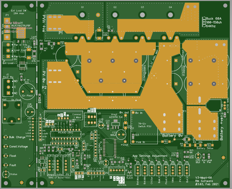
While waiting for the last 14M2 charge controller pcbs to come back, decided to do an upgrade to the design using the 20X2 chip, gathering the best features from previous designs to hopefully make a better controller. Using the 20X2 allows for 64 Khz pwm and extra capability; the higher pwm frequency will keep the inductor size down running at the higher charge currents.
For this higher power 60 amp design I have standardized the input\output cap's to the smaller 18mm dia foot print and more of them, each has a >3 amp ripple rating, this allows for better heat dissipation over the bulky 35mm types. The driver pcb is the same design as for the last 14M2 version and allows optionally a synchronous buck converter. Have expanded the removeable led display section to include a relay that is activated when in float charge mode and a 20 amp high side mosfet switch that is under cpu control, the load can be turned off on at low\high abnormal battery voltages.
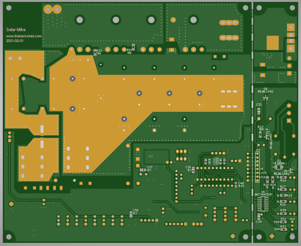
I have a number of common modules such as filters and 1-Wire comms. and have used them here to save pcb space and make it easier to build. The mosfets are mounted under the pcb as previous, but clamped to the heatsink by the pcb itself. For this prototype using 1oz copper pcb traces, have allowed for soldering some thick copper wire to the main high current areas.
Top: 196 x 160mm
Bottom:
Schematics soon..
Cheers
Mike