Guru
Joined: 17/05/2016
Location: United StatesPosts: 3358
| Posted: 12:00pm 09 Apr 2021 |
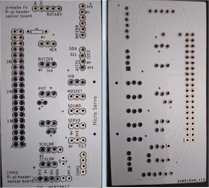
This PCB breaks out the pins of the CMM2 (r-pi type) 2x20 extension port. In the works is a hat PCB for the Armmite F4 which provides most of the functionality of the CMM2 extension port.
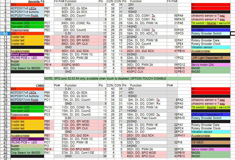
Connector pins are as follows for F4 & CMM2:
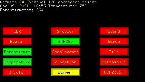
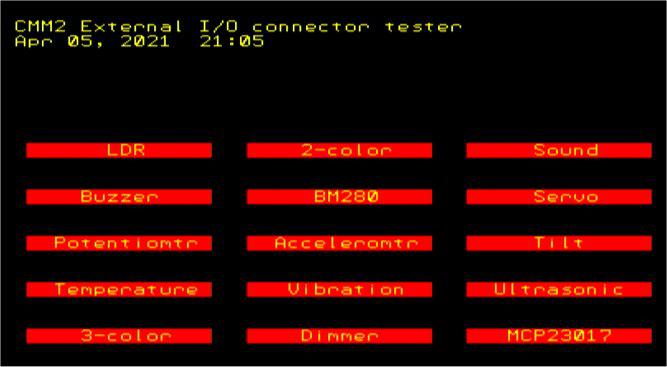
This demo is running on an F4 with a preliminary version of the hat PCB (with some fixes wired in). The display is a 4" SSD1963 480x270 LCD using matherp's 32-pin to 40-pin connector PCB.
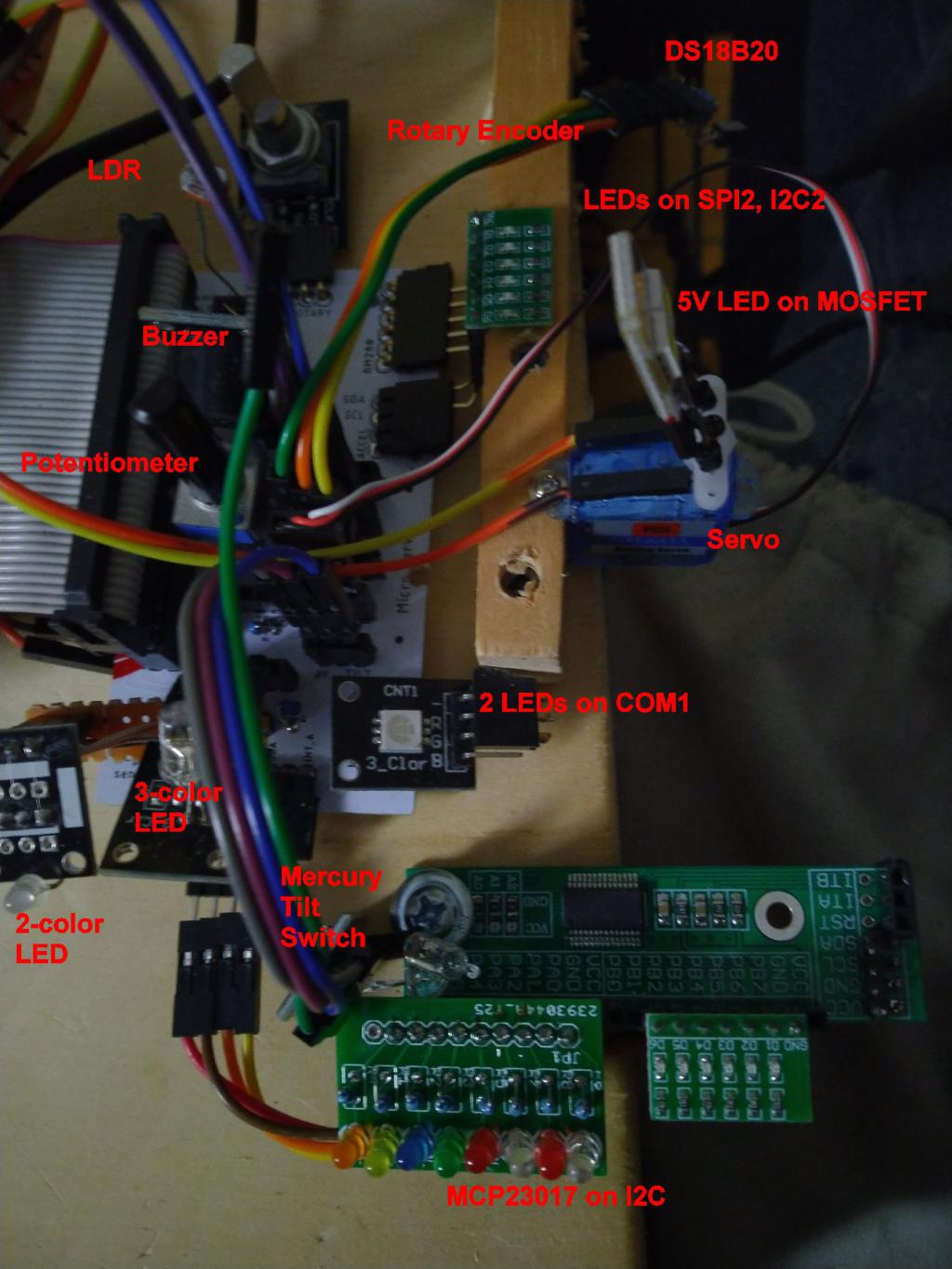
The modules plugged into the pin headers on the PCB include modules from the "37 sensors" type kits, plus a micro servo, an I2C MC23017 port extender, a MOSFET PWM dimmer module powering a USB 5V LED, and 6-pin and 8-pin LED modules.
Kit modules include a rotary encoder (which is used to select which modules are active), a DS18B20 temperature sensor, 2-color and 3-color LEDs, a potentiometer, and LDR, a buzzer and a mercury tilt switch.
Youtube video
(Sorry for the dead time in the video, and for the blurry images.)
The same code which runs this demo on the F4 also runs the same PCB on the CMM2, with display going to the VGA monitor instead of the LCD. Instead of the GUI buttons on the F4, the CMM2 displays text boxes.
A zip file of the gerbers for Version 2 (with additions, corrections, and adjustments) is attached. This can be sent directly to JLCPCB for PCBs.
The EagleCad sch and brd files are also attached.
The 3-pin headers for the "37 sensors" are in the typical orientation for those--0V,3V3,Signal, usually designated as "-", "+", "S". Those with analog pins need to have the 4th pin Dupont-wired to an analog pin.
Of course, many more of the "37 sensor" modules can be used, as well as other modules and sensors. More on that later.
sensors.zip
breakout 2x20.zip
rpi_sensor_breakout_2021-04-07.zip
PicoMite, Armmite F4, SensorKits, MMBasic Hardware, Games, etc. on fruitoftheshed