Guru
Joined: 11/12/2012
Location: United KingdomPosts: 10273
| Posted: 01:10pm 11 Jan 2022 |
No faults

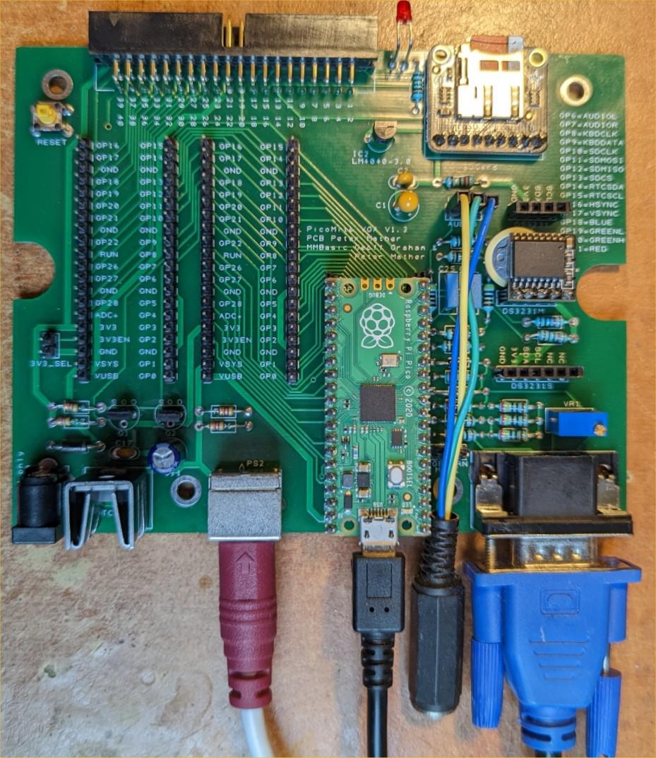
PicoMiteVGA.zip
ZIP contains a ZIP with the gerbers ready to send to JLC
Bill of materials, DesignSpark design files and printable schematic
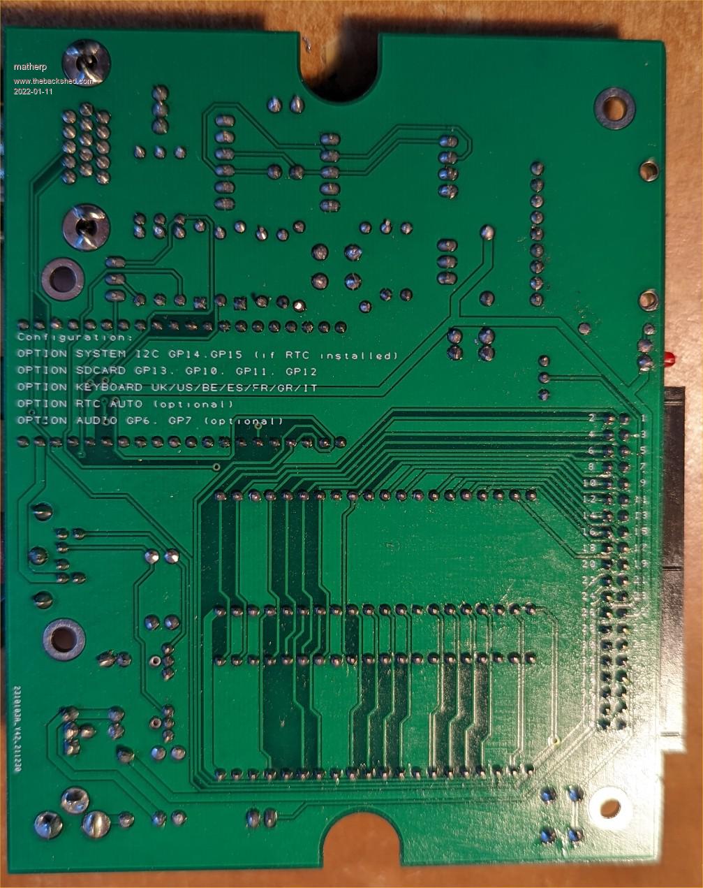
NB: lots of bits on the PCB are optional depending on use - see BOM for details
Edited 2022-01-11 23:18 by matherp
Guru
Joined: 31/01/2019
Location: GermanyPosts: 573
| Posted: 08:28am 12 Jan 2022 |
Thanks for your work . Mfg
Guru
Joined: 05/10/2019
Location: United KingdomPosts: 7889
| Posted: 09:07am 12 Jan 2022 |
Very nice board, Peter. :)
My mini version is currently partially back to design stage to make sure that it fits both variations of the 90x70x28 box that I have. It would be a pity to make it specific to one box, especially as you don't know which version will turn up!
Guru
Joined: 11/12/2012
Location: United KingdomPosts: 10273
| Posted: 11:25am 15 Jan 2022 |
Minor tweak to better centre the cut-out for the box
PicoMiteVGA.zip
Edited 2022-01-15 21:27 by matherp
Guru
Joined: 16/09/2019
Location: United KingdomPosts: 4308
| Posted: 11:25am 21 Jan 2022 |
Hi Peter,
A couple of questions on the BOM if I may:
For the SD card does R42 2R2 resistor really need to be 1% metal-film ? I already have the same value in 5% carbon-film. I have generally bought the carbon-film for hobbyist dicking about because I can read the colours easier.
For the Audio C25 and C26 I have 47 nf in a different (coloured) package, white and looking most like this https://www.ebay.co.uk/itm/142777705141 but with the marking "47n J100", are these any good to me - I've no idea where they came from.
Best wishes,
Tom
Guru
Joined: 05/10/2019
Location: United KingdomPosts: 7889
| Posted: 12:12pm 21 Jan 2022 |
The type of resistor for the 2R2 doesn't matter.
Your capacitors will be fine too.
None of these components are doing a precision job. It's nice (but not critical) if they will fit in the space though. :)
Guru
Joined: 16/09/2019
Location: United KingdomPosts: 4308
| Posted: 02:33pm 03 Feb 2022 |
Peter,
I'm not certain from the photo, but am I correct that the SD card breakout board is not attached to the PCB by a detachable pair of male and female 9 pin headers but instead it's permanently soldered to the board using just the male header ?
Best wishes,
Tom
Edited 2022-02-04 00:34 by thwill
Guru
Joined: 05/10/2019
Location: United KingdomPosts: 7889
| Posted: 03:17pm 03 Feb 2022 |
I'm not sure either, but soldering in the way you describe would certainly be more robust than using a female header. It's how I intend to mount SD card holders on my boards.
Guru
Joined: 30/06/2020
Location: GermanyPosts: 655
| Posted: 09:50pm 04 Feb 2022 |
I already ordered one last week in China, but still waiting to arrive. Why are three RaspberryPi Pico header in parallel?
Guru
Joined: 11/02/2018
Location: AustraliaPosts: 2626
| Posted: 10:20pm 04 Feb 2022 |
Peter added the two extra sets of pins so future internal modules could access any Pico pins. Making them the same footprint as the Pico means those modules could also be attached to a bare Pico.
Guru
Joined: 30/06/2020
Location: GermanyPosts: 655
| Posted: 11:37pm 04 Feb 2022 |
Thank you for the info phil! Great idea.