Guru
Joined: 30/03/2016
Location: United KingdomPosts: 1646
| Posted: 04:53pm 21 Sep 2022 |
Had one for a few years. Never plugged it in, had forgotten what it was for.

Craig
Regular Member
Joined: 20/09/2021
Location: CanadaPosts: 91
| Posted: 01:40am 24 Sep 2022 |
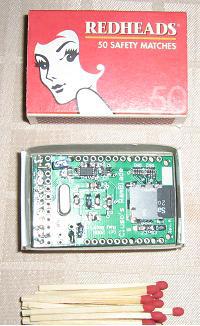
not quite sure if it'll fit in a matchbox, but a modern, cheaper equivalent might be ExtremeElectronics/RC2040: Z80 CP/M80 emulation of an RC2014 using the RP2040 (PI PICO) processor
Guru
Joined: 05/10/2019
Location: United KingdomPosts: 7865
| Posted: 06:53am 24 Sep 2022 |
I feel a challenge coming on... By surface mounting the Pico there's wasted space underneath. I wonder if I could make it smaller...? :)
No - leave it, Mick! You've got enough stuff going on at the moment! :)
That's a nice little board. I like the idea of emulating a RC2014, that's neat.
Guru
Joined: 30/03/2016
Location: United KingdomPosts: 1646
| Posted: 10:10am 24 Sep 2022 |
PGA-2040?
Or even one of the smaller alternatives if fewer pins would work

Craig
Guru
Joined: 05/10/2019
Location: United KingdomPosts: 7865
| Posted: 10:41am 24 Sep 2022 |
You can just squeeze a standard Pico onto a 50mm PCB (but you have to cheat by letting the Pico overhang slightly at the ends). Of course, you can always saw off the bottom end from a standard Pico if you want a few less pins. It's cheaper than buying a pre-crippled one and still works. :) I wouldn't want to go SMD 'cos it's hard when your eyes are c**p and your hands shake.
EDIT:
See here.. If you don't want buttons & switches it will run on a Pimorini Tiny 2040 (here) glued onto a SD card. Not bad for a CP/M machine. :)
Edited 2022-09-24 21:31 by Mixtel90
Guru
Joined: 05/10/2019
Location: United KingdomPosts: 7865
| Posted: 07:01pm 24 Sep 2022 |
Erm.... the decorating (and several other things) got put to one side a bit...
He said, guiltily.
48mm x 50mm using a standard Pico and no SMD parts (it's the usual uSD module with its own pullups and supply decoupling capacitor that I've used previously). The GPIO header is identical.
Slight changes:
Power is via VSYS rather than VBUS if powered from a serial port. GP22 is via a "buttons enable" link rather than hard wired on the pcb.
EDIT:
Decided it was a little plump, so some slimming exercises have brought it down to a lithe 43mm x 50mm.
Edited 2022-09-25 07:55 by Mixtel90
Guru
Joined: 05/10/2019
Location: United KingdomPosts: 7865
| Posted: 08:02am 25 Sep 2022 |
The slimline version on the left weighs in at 41mm x 50mm. This is built to the same circuit.
The flyweight, minimum version on the right is only 29mm x 39mm. All the non-essentials have been stripped off and power/console is only via USB. The Pico is a standard one, but the bottom end has been sawn off as not all GPIO pins are needed here. The LED and SOUND pins are the same, but the SOUND pins are also on the GPIO connector. GP0 and GP1, the serial terminal pins, could possibly still be used with a bit more messing about. The excess pin length on the SOUND connector, poking through the board, will almost certainly have to be carefully cut down as the uSD card holder has the metalwork immediately underneath them. Some insulation would be in order here. Still not as small as the Pimorini board, but a lot cheaper. :)
Edited 2022-09-25 18:06 by Mixtel90