Guru
Joined: 05/03/2018
Location: NetherlandsPosts: 5072
| Posted: 07:15pm 13 Dec 2022 |
chapter 2
- explaining the exercise with pin configurations
Last chapters exercise was about moving the 666Hz tone from pin GP0 to GP2.
You did not need to change the actual program, but only the configuration.
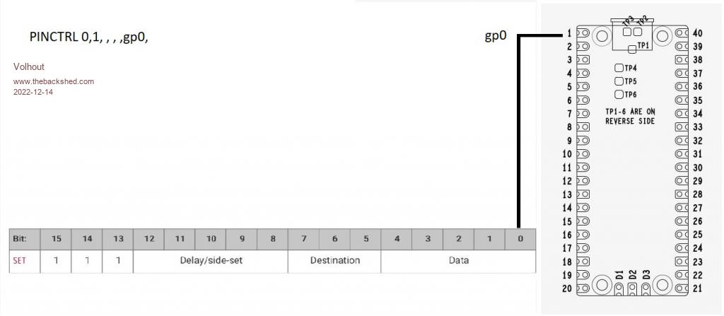
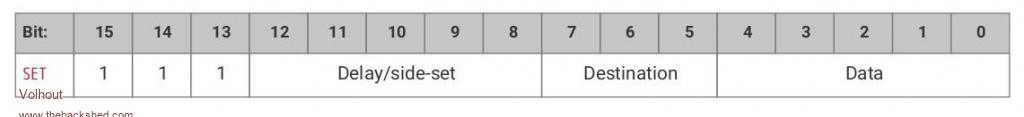
The starting point was the GP0 configuration, that links GP0 to bit 0 of the SET command.
You can assign more pins to the SET command by increasing the number of successive pins
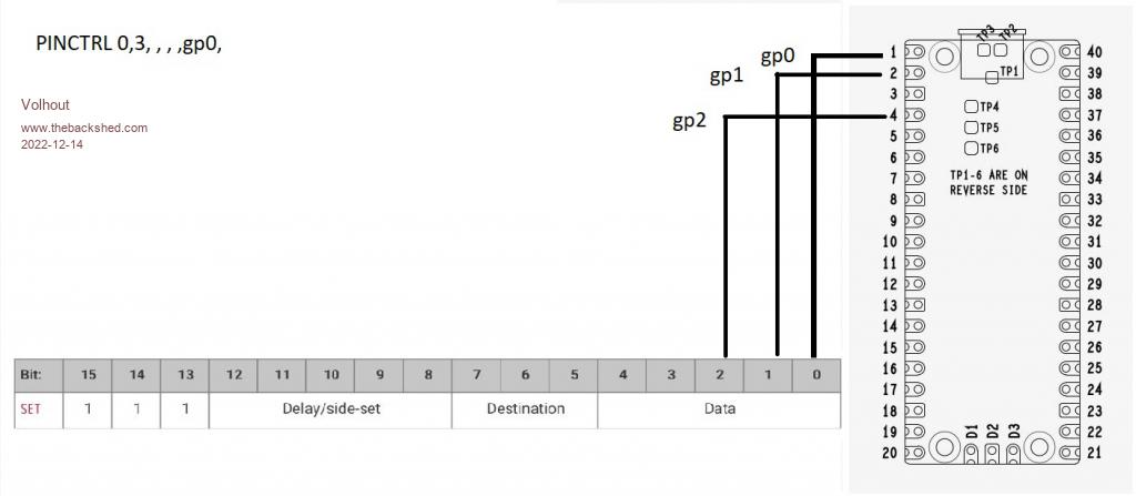
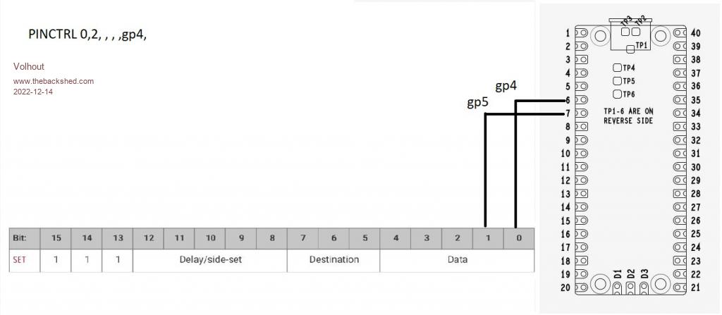
Or different pins, by selecting a different starting point
Knowing this the simplest answer is to assign 1 pin, named GP2.
And of coarse, you need to assign GP2 to the PIO1 in a SETPIN in MMBasic.
- explaining PIO INIT MACHINE
The MMBasic command PIO INIT MACHINE writes the combined configuration values to the state machine.
We have used the state machine frequency, and the state machine IO pin assignment (PINCTRL).
But there are more configurations, that will be explained on further chapters.
PIO INIT MACHINE a,b,c,d,e,f,g
a/ the PIO (in our case PIO 1)
b/ the state machine (0,1,2,3), we have used 0 in previosu exercise)
c/ the state machine clock frequency (2000Hz in our previous exercise)
d/ the pin control value (used in previous exersice to assigne GP0 to SET)
e/ the execute control register (explanation will start in chapter 3 and 8)
f/ the shift control register (will be explained in chapter 9 and 10)
g/ the starting address of the program for this state machine (was 0 in our previous exercise)
As you may have understood from the name PIO INIT MACHINE, each state machine needs it's won init. And has it's own PINCTRL and frequency. So one state machine can run at 2kHz, the other at 63MHz, both in the same PIO. And they can actually run the same code, just at different speed. But they can also run different code, depending the start address of the state machine.
- explaining PIO STOP
As you may have noticed when running the program in last chapter, the program ends, returns the comaand promt, but the audio tone from the PIO continued. That is the indication that the PIO operates independent of the ARM, and you need to force it to stop.
note: Peter (MMBasic) stops the PIO when you edit the program or restart the program.
The way to do that is PIO STOP a,b
a/ the PIO
b/ the state machine.
- new: execution speed and 666Hz
The state machine executes one program line in one clock cycle. The state machine in previous chapter was running at 2kHz (0.5ms). So if we analyze the program:
LINE а CODE а а COMMENT
0 а а &hE081 а SET PIN OUT 0.5ms
1 а а &hE001 а SET PIN 1 0.5ms
2 а а &hE000 а SET PIN 0 0.5ms
3 а а &h0001 а JMP 1 а а а а а0.5ms
After the SET PIN OUTPUT, the program runs a loop through adresses 1,2,3 then back to 1. A cytcle of 3 steps of 0.5ms. This makes the period of the output signal 1.5ms or 666Hz. But when we investigate what the GP0 pin is doing:
LINE а CODE а а COMMENT
0 а а &hE081 а SET PIN OUT 0.5ms
1 а а &hE001 а SET PIN 1 0.5ms high
2 а а &hE000 а SET PIN 0 0.5ms а low
3 а а &h0001 а JMP 1 а а а а а0.5ms а no change -> low
It is high 1/3 of the time, and low 2/3 of the time. That is not a nice square wave. For a nice 50% duty cycle we have the option to stretch the high level to 2 cycles. There are several options
- new: DELAY field
1/ Add a dummy instruction (reapeat the same instruction, or add a NOP
0 а а &hE081 а SET PIN OUT 0.5ms
1 а а &hE001 а SET PIN 1 0.5ms high
2 а а &hE001 а SET PIN 1 0.5ms high, a dummy instruction
3 а а &hE000 а SET PIN 0 0.5ms а low
4 а а &h0001 а JMP 1 а а а а а0.5ms а no change -> low
2/ Add a delay of 1 clock cycle to the SET PIN 1 instruction. This is where the DELAY field of the SET instruction plays a role.
The delay field allows up to 31 (5 bits) clock cycles delay after the instruction is executed.
If we want 1 extra clock cycle delay in the SET PIN 1 then this becomes
1 а а &hE101 а SET PIN 1, dly=1 1ms high
аAnd out program looks like this:
а
LINE а CODE а а COMMENT
0 а а &hE081 а SET PIN OUT а а а а0.5ms
1 а а &hE101 а SET PIN 1 dly=1 а а1 ms а аhigh
2 а а &hE000 а SET PIN 0 а а а а а0.5ms а low
3 а а &h0001 а JMP 1 а а а а а а а0.5ms а no change -> low
а
Now we have a loop of 3 instructions, but 1 instruction lasts 2 cycles, so the loop is 2ms (500Hz).
The frequency can be measured using the MMBasic frequency measurement function, as suggested by phil99. I used GP8 to do that since it matches my breadboard better.
'disconnect ARM from GP0
setpin gp0,pio1
'configure pio1
p=Pio(pinctrl 0,1,,,,gp0,)
f=2000 'Hz
'pio program
'line а code аcomment
' 0 а а E081 аGP0 output
' 1 а а E101 аpin high, dly=1
' 2 а а E000 аpin low
' 3 а а 0001 аjmp 1
'program pio1
pio program line 1,0,&hE081
pio program line 1,1,&hE101
pio program line 1,2,&hE000
pio program line 1,3,&h0001
'write the configuration
PIO init machine 1,0,f,p,,,0
'start the pio1 code
PIO start 1,0
'Check the frequency in MMBasic
Setpin GP8,FIN
pause 1000
print pin(gp8);" Hz"
PIO STOP 1,0
END
- new: ARM spying on PIO output
Peter has provided the possibility to let the ARM spy on PIO outputs. Normally you would get an erro message in case you try to read a pin that is assigned different, but for PIO he made an exemption.
Since MMbasic is quite fast you can read the pin in a loop, and see the levels the PIO is putting out.
From the output you can see that the duty cycle is 50% (as many 1's as there are 0's).
'disconnect ARM from GP0
setpin gp0,pio1
'configure pio1
p=Pio(pinctrl 0,1,,,,gp0,)
f=2000 'Hz
'pio program
'line а code аcomment
' 0 а а E081 аGP0 output
' 1 а а E101 аpin high, dly=1
' 2 а а E000 аpin low
' 3 а а 0001 аjmp 1
'program pio1
pio program line 1,0,&hE081
pio program line 1,1,&hE101
pio program line 1,2,&hE000
pio program line 1,3,&h0001
'write the configuration
PIO init machine 1,0,f,p,,,0
'start the pio1 code
PIO start 1,0
' check the GP0 pin from MMbasic
'array to store 101 samples taken from GP0
dim v%(100)
'sample the GP0 pin into the array 101 samples
for i%=0 to 100
аv%(i%)=pin(gp0)
аpause 0.1 а а а а а а 'limit the speed a bit
next i%
math v_print v%() а а а 'print the whole array to the screen
'stop pio
PIO STOP 1,0
END
RUN
0, 0, 0, 1, 1, 1, 1, 1, 1, 0, 0, 0, 0, 0, 0, 1, 1, 1, 1, 1, 1, 0, 0, 0, 0, 0, 0, 1, 1, 1, 1, 1, 1, 0, 0, 0, 0, 0, 0, 1,1
>
>
0, 0, 0, 1, 1, 1, 1, 1, 1, 0, 0, 0, 0, 0, 0, 1, 1, 1, 1, 1, 1, 0, 0, 0, 0, 0, 0, 1, 1, 1, 1, 1, 1, 0, 0, 0, 0, 0, 0, 1,1
>
>
- new exercise
Last time the exercise was pretty easy. This time we'll make 2 exercises, you can pick any you want, or both. They are about the current knwledge.
#1: please adapt/write a program that outputs a nice 50Hz frequency from GP0. Note that the clock frequency for the PIO cannot go below 2kHz (at 126MHz CPUSPEED.
#2: As you may have seen, Tom (thwill) bought buzzers that have a resonant frequency of 2.7kHz (they are most loud at that frequency). If this where a piezo, you need to drive it with high voltage level. This can be achieved by driving each pin of the piezo with a different IO pin. The second IO pin must be out of phase (180 degrees). This essentially is inverting the second pin.
Happy programming.....
Volhout
Edited 2022-12-14 05:44 by Volhout