Hopefully? Another 48vdc-240vac Toriod Inverter build.


Author Message
tinyt
Guru

Joined: 12/11/2017
Location: United States
Posts: 435
Posted: 12:52pm 06 Jun 2023      

  KeepIS said  ..
I set a DSO up to measure the voltage across a Resistive shunt on CH1 and compare it to the Current Sensor on CH2.

I wanted to see if the shunt could be used to get an accurate reading of Peak input current at high current.

The shunt calibration is 75mV = 200A.

I though that starting a 420A peak load through the Shunt might make it easier to get a good result above the switching noise on the DC input.

It's still very difficult. Where the Hall Sensor produces a perfectly clean DC sinewave as it follows the Inverter input current, the Resistive shunt has a lot of transients and is not consistent in amplitude from cycle to cycle.

The Sensor indicates 420A across the startup surge waveform, the Shunt is indicating anywhere from 430A to 560A.

You might get a ball park figure from the shunt, but that's about it. If I find a way to get a consistent result I'll post it.

EDIT:
When starting a load drawing 570A Peak DC, the shunt displayed this 590A on the cleanest waveform cycles, but you have to understand clean in this context, but once again it was also showing values of over 700A on other cycles. Really useless, and looking at the waveform I doubt a resistive shunt even with filtering would be reliable at these high currents through DC cable.

You really need the galvanic isolation provided by the HALL effect Sensor.  

FYI: The Precision Peak Circuit and Meter showed just over 400A on the 420A startup and hit just over 550A on the 570A start. Dam that's good.
.


I thought I can use the existing shunt jumpers and opamp (IFB) on the chinese inverter board I am using.
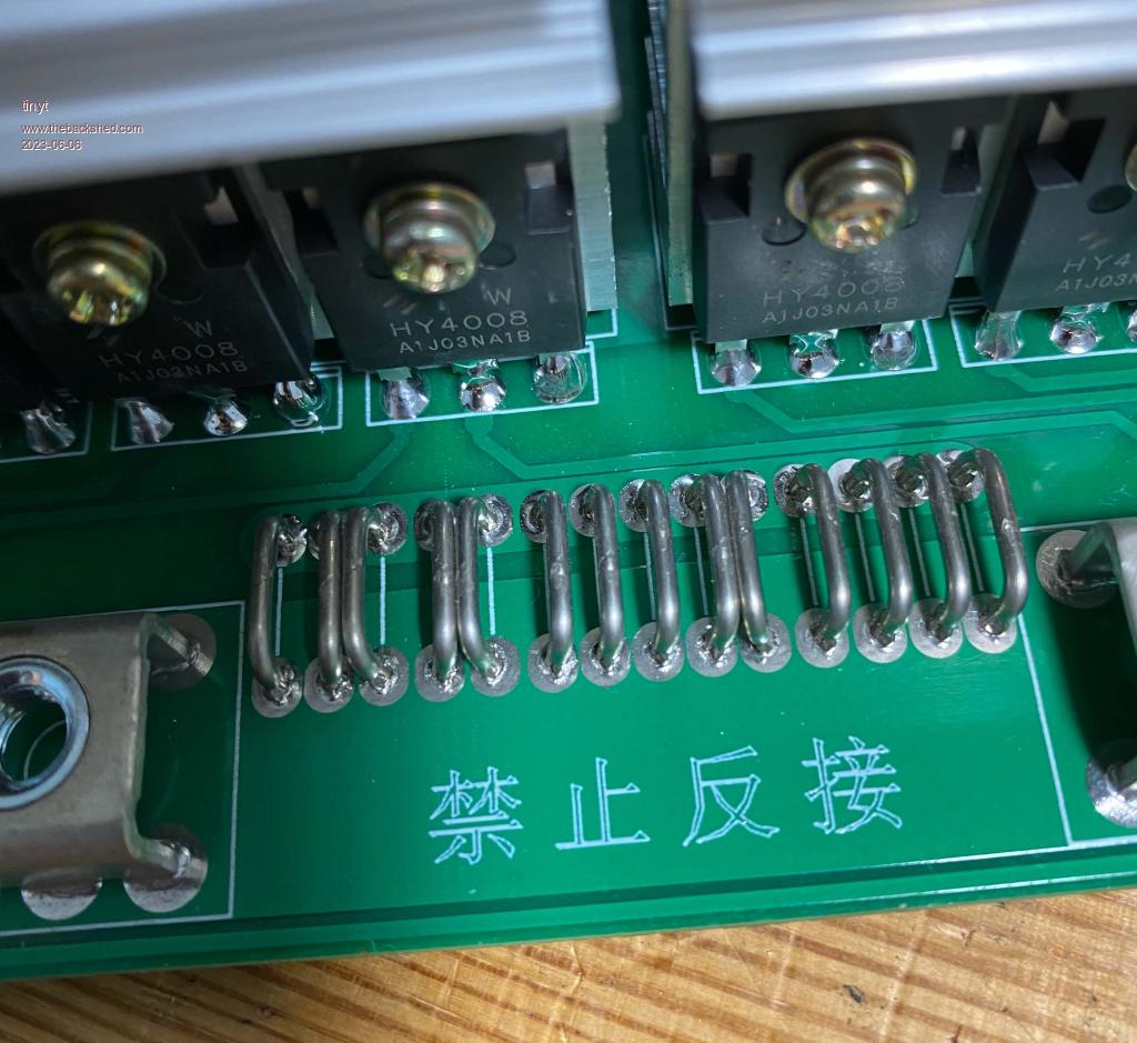


Also, doesn't the bulk electrolytics on the power board filter out the sinewave current?