Senior Member
Joined: 11/01/2024
Location: PolandPosts: 101
| Posted: 08:48am 06 May 2024 |
Update regarding the MPPT system - I soldered new SiC B2D30065H1 diodes (52A continous current @ Tc=135°C), two pieces per module. Now MPPT works and survived tests
 So far, the highest power from MPPT that I have seen is ~2kW - the pv panels did not allow more yet.
As for the inductor, I personally checked it in several calculators, which suggested a certain minimum inductance value.
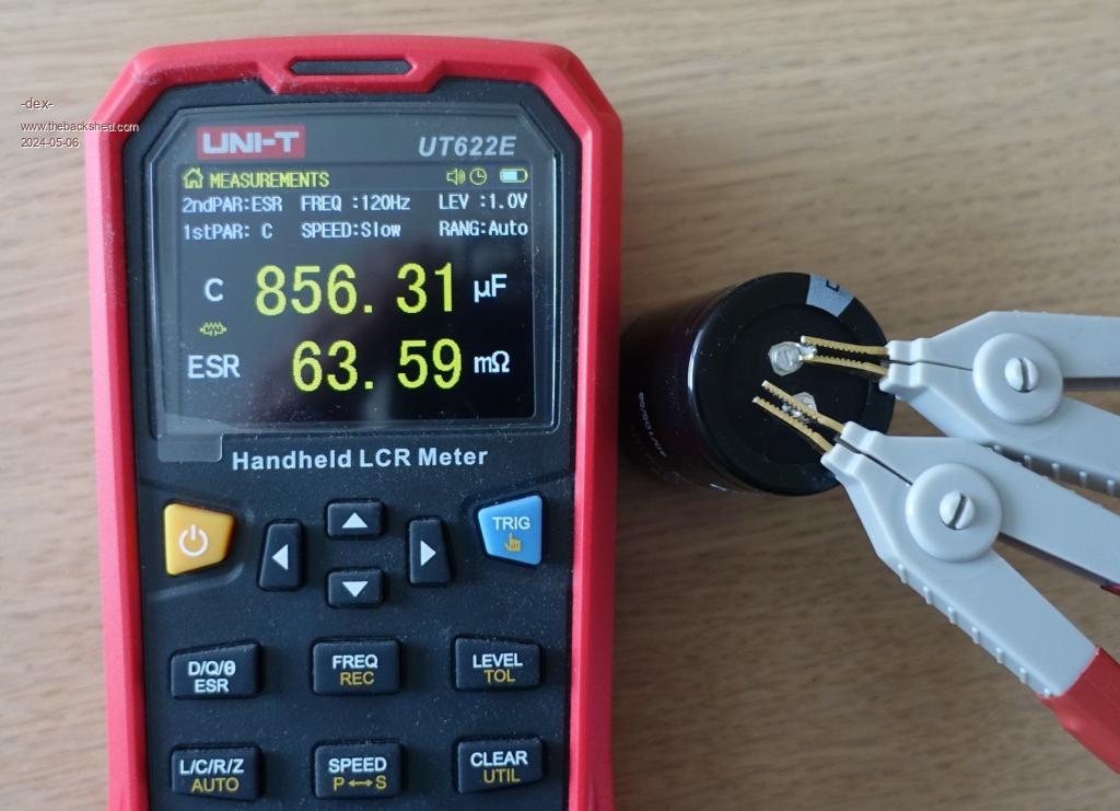
For the capacitance value of the capacitors, I was not able to calculate it. I did what was advised here - "any reasonable capacity value will do" or use what you have on hand. My capacitors are several-year-old storage units, measured parameters in the photo.
Can anyone calculate what capacity value will be safe?
Is it possible to approach it from the other side and appropriately oversize the mosfet and diode for this event?
In my mpppts all PV side & output side capacitors are 300V rated.
So if one mppt has a shorted mosfet, it sends ~100V to the outputs of the other mppts. While other mpts runs, get 100V at ther outputs, they are safe or not?
I also saw in your built that you used diodes in series to connect the MPPTs, in this situation should block the high voltage from reaching the other MPPTs.
Back to protector & kilovac
I used this kilovac in my inverter. I will use the same model in OVP protect circuit on the MPPT bus. The G version is available in digikey, 48V coil with economizer.
AEV250_2.pdf