Senior Member
Joined: 11/01/2024
Location: PolandPosts: 101
| Posted: 06:03am 09 Jun 2024 |
Good morning!
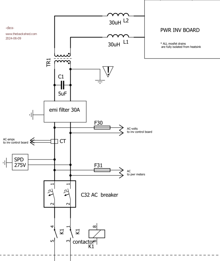
So I'll refer to the first answer. There are basically 3 components on the AC source - input pin route on the controller board:
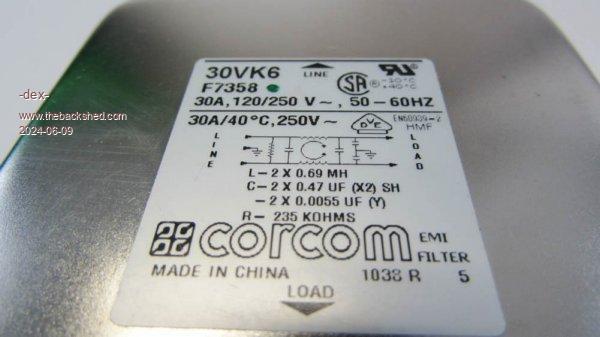
1. EMI filter
2. Fuse
3. Ferrite beads
Everything is connected as in the diagram.
Both meters on din rails and the "inverter's meter" wires are connected at one common point.
RV1 behaves correctly, I can change the input voltage with it. But why does the system do nothing to change the SPWM % when the AC voltage drops?
I could observe large changes in % SPWM in case of significant changes in the DC voltage on the power rail.
Edited 2024-06-09 17:16 by -dex-