Senior Member
Joined: 11/01/2024
Location: PolandPosts: 101
| Posted: 12:54pm 25 Jun 2024 |
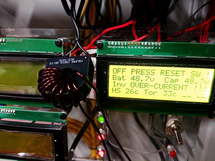
Setting up OCP
The inverter current sensor was initially calibrated to approximately 6kW of power. In such a configuration, starting any power tool (saw, hammer) or a larger SMPS power supply activates the OCP and forces user intervention to restart the inverter. The overload detector is very fast and sensitive.
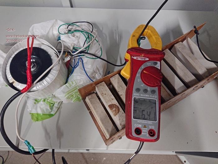
Mike advised setting the current sensor value to twice the current of the mechanical fuse breaker. In my case, the AC breaker at the inverter output is 32A, so for calibration we need 64 AC on the current sensor.
There is a simple trick here - wind 10 turns on the current sensor, then you need to get 10x less current. I did it using an 8ohm resistor and a toroid transformer whose voltage I selected to obtain a current of 6.4A (I don't have a variac)
Now all you need to do is set the RV2 potentiometer in the right place. The adjustment range is sufficient.
The TEST MODE was very useful here - there is no need to remove the board, and you can adjust the overcurrent with the inverter turned off.
I don't want make an intentional short circuit on the AC side for testing purposes to see if it works I mean whether the first mechanical fuse or the OCP inverter will trip, if at all

Edited 2024-06-25 22:54 by -dex-