Senior Member
Joined: 11/01/2024
Location: PolandPosts: 101
| Posted: 12:53pm 26 Jul 2024 |
It's been a while since I posted anything in the thread about the construction of my inverter. Recently I have been doing something else, and the description of the structure is late compared to the current state.
I will come back to the battery and BMS.
I've previously written about the terrible lifepo4 startup failure and battery explosion. This made me afraid to touch the cells any further, everything was dismantled and put back in cardboard boxes.
I discovered that the short circuit was caused by incorrect compression, which resulted in damage to the blue insulation which short to the inverter casing. There were also no spacers between the cells and no BMS protection.
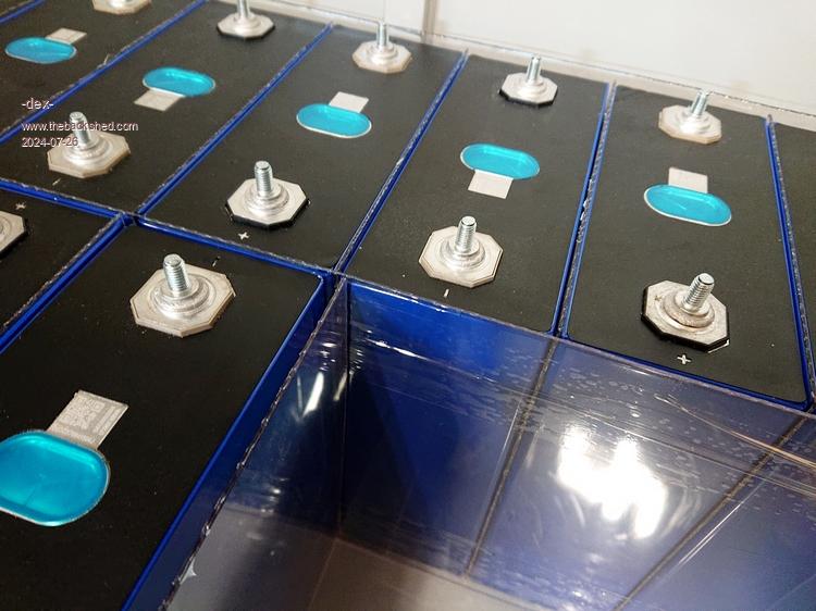
When the dust settled, I ordered some new cells - I actually have to buy them in multiples of 4, that's how they come in packs of 4 and Chinese sellers don't sell one. I put together a package of 16 cells again. I measured each cell's internal resistance, which is extremely low. Even the one that was damaged (go back to previous posts - melted battery terminal, damaged casing, electrolyte leak) had the same resistance and voltage as the other cells
 !!! But I replaced it with a new cell anyway.
This time, everything is insulated: the bottom on which the cells sits, the sides of the pack, and each cell are separated with 1.5 mm thick plexiglass. This time I don't use any compression. The reason for the lack of compression will be discussed later.
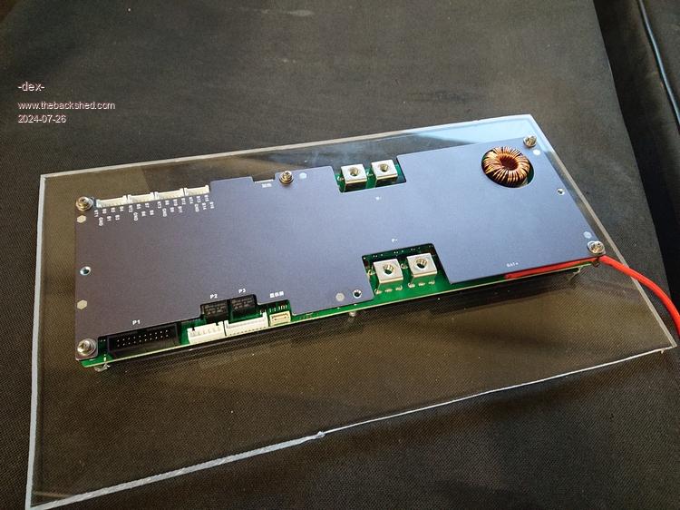
I added further layers of protection: BMS with overcurrent protection for charging and discharging, voltage control and each cell separately, and an active 2A balancer. Moreover, in the middle of the series I placed an additional fuse with a value of 120A - if there was a short circuit at the battery terminal itself, it would burn out.
The BMS is configured via a smartphone application and connects via Bluetooth. It also has wired communication, which I would like to use in the future to present battery data, mainly battery's SoC, in my building automation system. I also have a large touchscreen display for it, placed next to the other LCD displays.
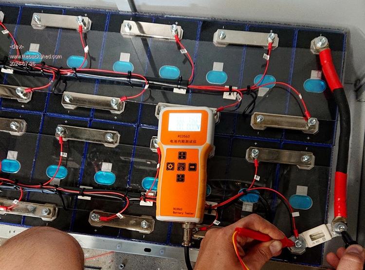
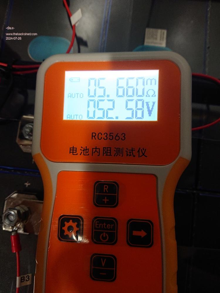
In the last photo you can see the resistance of the entire package thus cells and all connections between them, which is measured at the + and - output of the 51V battery. When you do the math, you'll see what a brutal force can it be

Edited 2024-07-26 22:57 by -dex-