Senior Member
Joined: 11/11/2021
Location: United StatesPosts: 148
| Posted: 07:02pm 01 Dec 2024 |
Thanks for confirming. Large lithium based battery banks indoors make me nervous

Guru
Joined: 13/10/2014
Location: AustraliaPosts: 1873
| Posted: 04:20am 20 Dec 2024 |
Lots of rain and overcast days with 34°C temperatures and unbelievable humidity.
The Hot water system is running beautifully on the inverter under these conditions and absolutely no problems for the battery bank and existing solar over a few days of this bad weather.
I've had the inverter running at 4kW when starting the biggest work-shed loads, the peak DC input currents are hitting over 730A, once the extractor startup load settles the running load is at 5.2kW, the next piece of cutting machinery is started and stopped around 20 times for for a few hours, each start is another 390A Peak DC above the running 5.2kw running load.
The results - well nothing happens, the Inverter remains silent, the Toriods never get above 39°C so cooling fans never come on, and the Heatsink temperature rise is around 2° on each heatsink (convention cooling).
Keep in mind that the Inverter is running an AirCon which is keeping the room that the inverter is located in at around 28°C and of course removing the Humidity.
I've had one fault (which does not affect the inverter), one digital DC input meter has lost it's display, back light still works - it's a few years old so I guess it's time to replace it. I might break it open and have a look, but easier to replace it really.
So, now it's time to pull the old Hot water controller panels down and replace them with higher power panels for more solar to the Inverter, I'm also going to put another 6kw of solar facing slightly south on the back of the shed roof for those overcast rainy days, panels don't care where they face in those overcast conditions.
This paralleled output stage Inverter is simply amazing.
_
Regular Member
Joined: 28/05/2024
Location: PortugalPosts: 79
| Posted: 07:51pm 20 Dec 2024 |
I have received my boards from wiseguy looking forward to doing my build in he new year.
Any update on getting the the real-time display working with home assistant. Would live to see the LCD info show up in a home assistant display.
Perhaps a hard wire solution.
Guru
Joined: 13/10/2014
Location: AustraliaPosts: 1873
| Posted: 05:36am 10 Feb 2025 |
I've knocked together a few PDF files from information spread across the build threads to help with setting up the Nano for programming and some Menu info.
The Zip below includes info and links to the low cost programmer board used for the Nano and various mods for a few of the Nano PCB models to stop the USB controller from causing a reset to a running Nano Inverter, also included are the Terminal Setup and Nano Fuse settings howto and using the small AVR program below.
So, for anyone interested, the Zip include the Inverter HEX files and the small standalone AVR program used to upload the Hex file to the Nano.
Link Download ZIP
.

Guru
Joined: 31/12/2016
Location: AustraliaPosts: 1153
| Posted: 10:21am 11 Feb 2025 |
Thats great to have it in one place (folder),
 I printed out the Menu How To.
Guru
Joined: 13/10/2014
Location: AustraliaPosts: 1873
| Posted: 10:13pm 11 Feb 2025 |
Thanks Aaron, it's a bit rough but I hope to add to it and improve it in the future.
FYI, I've updated the Download with 4 PDFs merged into one, also some minor text corrections.
Footnote added 2025-02-12 11:55 by KeepIS
I have also combined and added more info to Menu usage and Terminal setup.
Guru
Joined: 13/10/2014
Location: AustraliaPosts: 1873
| Posted: 01:40am 16 Feb 2025 |
I was looking at the Photos of Aarons build (Revlac) and I noticed I still has not updated the top line of the Inverter LCD display.
I've just done that on both Dual and Single versions of the Code and download has been just updated. No other changes.
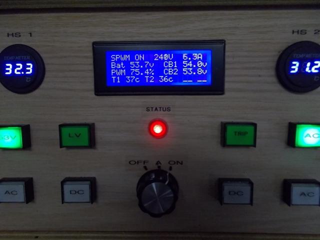
I felt that indicating when SPWM drive was enabled was more important to me than an indication of the Start/Stop request flag which was either ON or OFF, especially since any error that could inhibit the inverter Start/RUN cycle is clearly indicated on the LCD, there are around 18 fault condition messages and that's not including the various LCD I-O status indications.
Full Zip with Nano Info
Just Hex files
Just an FYI update, I have uploaded updated zips with a lot more information for the settings in the Battery Menu options block:
8: Battery <-> Cap delta:
9: Battery low-V disable:
A: Battery low-V timeout:
B: Battery low-V restart:
C: Battery restart delay:
D: Battery HighV disable:
The new file in the Zips is called "Menu Battery Settings.pdf"
.
Edited 2025-02-23 10:58 by KeepIS
Guru
Joined: 13/10/2014
Location: AustraliaPosts: 1873
| Posted: 04:36am 25 Feb 2025 |
I've updated the "Full download" with more Information on the Programmer board and the installation of the Driver for the board, this is in the "Nano Board Info.pdf".
I've also include the Driver Install application in the ZIP.
FYI: The Toroid rings I used for the last two chokes are AS225-125A ferrite toroidal rings.
I ordered some more just in case from a different supplier, these arrived correctly packed, each ring bubble wrapped and all rings packed in a large box with bubble wrap inside. Ordered on the 14th Feb and delivered today 25th Feb.
AS225-125A ferrite toroidal rings AU-$7.47 inc tax, free shipping.
Link to Ferrite Rings
Ideally you want 9 of these rings for a single 4 turn 23uH high saturation choke. A smaller inverter could get away with six per choke and another turn or two.
NOTE: You need two chokes per inverter, yes the inverter will run with one choke, however two chokes of 23uH each reduce the size of a single 46uH choke choke, most LF Inverter will require a total choke inductance of 39uH to 46uH.
.
Edited 2025-02-25 18:09 by KeepIS
Senior Member
Joined: 11/12/2020
Location: CanadaPosts: 112
| Posted: 01:59am 27 Feb 2025 |
Thanks for the link for the Sendust cores. In Canada, the price comes up as $6.60 plus $9.45 shipping (CAD), but as you add more cores, the shipping just goes up by $1 each.
(until you hit 12 cores when the shipping goes up by an additional $60)
So to order 11pcs it works out to $8CAD or $8.84 AUD each which is the best price I have found around!
I tried ordering this size core earlier off an EBAY vendor, but they ended up not actually having the advertised cores and sent me MS184040-2 cores instead.
They refunded me, and I may use the cores for something, but obviously not ideal.
On another note, when I enter a stack of 9 pcs of this core (MS225125-2) with 4 turns in the Micrometals inductor Analyzer,
I am not seeing the inductance at the higher currents you are mentioning.
On my previous builds using 3xMS157060-2(Sendust) and 4xT250-40(Iron Powder) the inductor Analyzer numbers were surprisingly close to the numbers
I measured using a storage scope and high current source. Obviously what you have is working well, so just wanted to confirm that you are using
these cores with just 4 turns.
Here is the current vs inductance curve generated for a stack of 9 MS225125-2 cores with 4 turns.
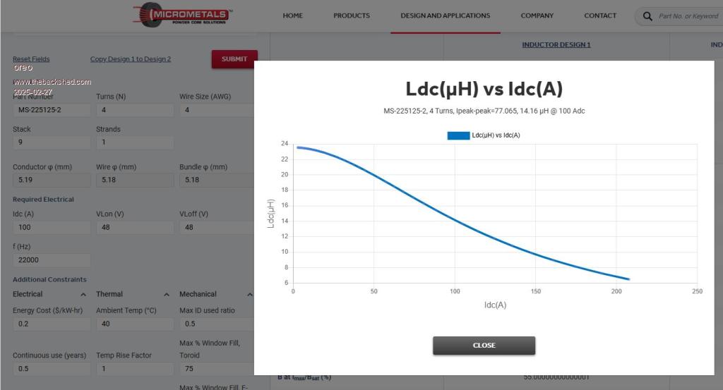
I have double checked the core weights and sizes between the Micrometals core and the Aliexpress core and they match. So I am a little stumped with why the difference.
Guru
Joined: 13/10/2014
Location: AustraliaPosts: 1873
| Posted: 02:23am 27 Feb 2025 |
That's interesting, I'm measuring them with a current source of up to 700A and a DSO, while they are not "quite" as good as the meatier 6 core stack (not available) they are close.
These are measured with a high current hall effect sensor and confirmed against a resistive shut for Hall Sensor transient response and indicated current.
Two chokes have been repeatably subjected to almost 600A daily for over a year, and as you say, they are working well, in this dual inverter they now see 600A peaks across 4 chokes.
It's a shame that we can't get the original cores, and cores in general at a decent price.
Edit: From memory I calculated around 9uH at full current for a single 9 core choke with original thicker cores, if the Sim is correct then I was close, 7uH @ 200A single choke, two chokes would be round 14uH at 400A, over 20kW input surge.
.
Edited 2025-02-27 13:36 by KeepIS
Senior Member
Joined: 11/12/2020
Location: CanadaPosts: 112
| Posted: 04:02am 27 Feb 2025 |
Are you seeing inductance go down when the DC current goes up? If not, then these must not be Sendust cores.
Guru
Joined: 13/10/2014
Location: AustraliaPosts: 1873
| Posted: 04:52am 27 Feb 2025 |
Of course, why would they be 23uH at zero current and 9uH close to saturation.
They are Sendust, the correct mix is stated.
Guru
Joined: 13/10/2014
Location: AustraliaPosts: 1873
| Posted: 08:35am 27 Feb 2025 |
FYI Update: I have added more Menu information and updated and Consolidated Menu and other PDF files into a single file inside the Full download. See signature below.
Edit:
Finally got the information into a single PDF with a Linked Index, even though the PDF creation program I'm using is an absolute dog. That's it for now.
As I find errors and make additions, the links in the signature below will be updated
.
Edited 2025-03-02 08:55 by KeepIS
Guru
Joined: 13/10/2014
Location: AustraliaPosts: 1873
| Posted: 12:20am 03 Mar 2025 |
I noticed the information on installing the Driver for the Small programmer board using Zadig was incorrect

I have updated how the Programmer board appears under Device Manager and added the Driver Properties information as it appears in my system, this may be of some help.
Usually the driver install is easy, but sometimes thing don't go according to plan.
EDIT Added info on the ADC A7 modification.
Fun times ahead, looks like this cyclone is coming ashore around 20km to the East of our property, spent the day checking solar panel mountings and trying to secure everything around the yard, gale force winds expected to be "full on" for over 10 hours

.
Edited 2025-03-04 16:11 by KeepIS
Guru
Joined: 13/10/2014
Location: AustraliaPosts: 1873
| Posted: 04:16am 09 Mar 2025 |
Had some quite strong winds here but not much rain, solar panels are still there.
I've been switched over to Mains priority at night during this event to ensure I have 100% batteries, this allows running two fridge/freezers, lights, starlink internet, TV laptops etc, for at least 4 days "or more" of dark cyclonic weather without relying on Mains power when it goes down for an extended period.
And - power went down (night time of course) I didn't even notice, I was watching some scary movie, as you do when the wind is howling outside, during that time the power failed, the change-over to Inverter power was seamless, I only noticed it when I looked outside and found I was the only one with security and normal house lights on.
Now waiting for the rain to clear so I can clean up a few branches and leaves and put everything back that had to be locked away or tied down.
FYI: I've made a change to the code for Terminal Menu refresh. Now adjusting and calibrating voltage or current readings will force the Terminal Menu to be refreshed automatically "after the ADC values have been processed", there is no delay in the Menu redraw, it's just timed correctly.
Hope anyone hit by this Cyclone came through OK
Guru
Joined: 13/10/2014
Location: AustraliaPosts: 1873
| Posted: 06:40am 15 Mar 2025 |
High current draw then Short on Inverter AC line.
I came back to the house after a morning walk to find no power (off grid), the Inverter was averaging around 6kW when I left.
Looking back at the LOG, an Unknown fault on the AC wiring had caused the DC input to run over 17Kw, over 30kW peak, into the Inverter for at least 6 minutes.
I was glad to find the Inverter was still happily idling with no error and showing 243VAC output, the Inverter AC output runs to a double pole DZ47-C63 circuit breaker, and this had tripped after around 6 minutes running time at high AC current.
I switched the 63A circuit breaker back on and it instantly tripped again.
This time the Inverter also tripped with an over-current fault indicated on the LCD.
Two DC input current trip LEDs were ON, one on each DC input feeding two Power boards, but no AC current trip, Inverter AC current trip is set at 73A from memory.
I reset each DC trip indicator/button and pressed master reset - leaving the 63A AC circuit breaker off.
The Inverter powered up perfectly, tough little bugger.
I switched over to Mains power and the changeover switch visibly arched on connect, normally there is NO visible ARC, Mains power tripped another breaker as it switched.
It appears there might be a short or arching across a socket or fault in some powered on equipment?
I checked external power points for water ingress etc, powered everything off and switched the Mains AC breaker back on, this time nothing tripped, finally powering everything back on without a problem.
Switched from Mains AC back to Inverter AC power and everything is running perfectly.
It's possible I had a Gecko in the Inverter-Air-Con, happened before, but the AIR-CON powered up fine this time, or the third time that AC was switched on, it might have cleared a short of some kind?
Recap, a high current draw that was not a complete short caused a 63A AC breaker from the Inverter to trip, the fault on the AC line (now a short) instantly tripped the Inverters 63A AC breaker when I reset it, this caused the Inverters DC input protection to trip, the Input protection is designed to trip at 850A Peak DC input, and it did that without fazing the Inverter at all.
We had the Cyclone go through here a week ago, but I did not find any sign of water ingress after it, and Inverter has been running perfectly for a week of fine hot sunny days ?
.
Edited 2025-03-15 16:46 by KeepIS
Guru
Joined: 11/02/2018
Location: AustraliaPosts: 2620
| Posted: 07:34am 15 Mar 2025 |
About 2kWH has been dumped into something! Your microwave can cook a meal with about 0.5kWH so what ever it was will have got extremely hot, possibly damaging things around it.
It may be worth opening up everything that was live at the time.
The mains is good at blowing resistive faults clear (if it doesn't start a fire!) as the peak current can be many hundreds of amps. At my switchboard the supply impedance is 0.3Ω so a fault peak could be over 700A.
You can get an estimate of your supply impedance by switching a 10A heater on and off, measuring the change in the mains voltage. Repeat a number of times and get the average (the mains voltage is always fluctuating a volt or two, masking the change to some degree). The impedance is delta V / delta I
Guru
Joined: 13/10/2014
Location: AustraliaPosts: 1873
| Posted: 09:00am 15 Mar 2025 |
I know what was running and what was on standby, so they were easily checked, all are fine. Anything on standby would have gone up in smoke if a standby circuit had shorted.
That power level is unheard of in this system, the maximum load I can reach is around 9kW. The logging sensors are independent of the Inverter, when the Inverter C63A AC breaker was switched back on the first time, the DC current input to the Inverter kissed 800A.
I believe the fault was coming from the Shed AC circuit, this has two external weather proof power points with a Big water Pressure Pump from the Tanks and a Hot water System, both were checked and everything was dry, and both work correctly.
The washing machine was running on heat cycle, I turned that off before the first attempt at Mains along with the Pump and W-Heater which had been running, and it still blew the AC breaker.
The power was an additional 11kW above the max normal load for that time.
We will see how it goes overnight - I'm calling it a day and heading over to watch a movie.
Thanks again for the input. I will go through everything in the Workshop tomorrow just to be sure.
BTW the Shed circuit from the main Fuse box is extremely heavy cabling as it needs to start and run a number of large workshop Induction Motors on top of the normal workshop high running loads, which it does easily with very little voltage sag.
.
Guru
Joined: 21/06/2018
Location: AustraliaPosts: 1206
| Posted: 10:54am 15 Mar 2025 |
Is it possible a compressor or similar was connected at the time? As they will only start after an extended slow leak it is not immediately obvious if it tried to start. I once tried to start my compressor using inverter soft start but it killed my first inverter. The compressor/motor started to turn starting slowly but it stalled at the first compression part of the cycle and with no flywheel effect to ride it through the compression stroke it growled louder and louder until there was a bang and smoke (Hy4008s lol). The whole process was over within a few seconds, except for the PCB repair
 .
. Senior Member
Joined: 11/11/2021
Location: United StatesPosts: 148
| Posted: 10:46pm 15 Mar 2025 |
 Good thing nothing was damaged and you were able to verify the protection mechanisms worked as designed. So, this mean the inverter can run 17kW for at least 6 minutes?