Guru
Joined: 13/10/2014
Location: AustraliaPosts: 1877
| Posted: 06:07am 04 Mar 2024 |
The focus of this thread is to help forum users who may be new to Inverters and unsure of where to start with building one, hopefully showing how easy most of it is.
There are many boards and variations on this forum, and this build is a smaller Inverter of the same design as my main inverter. I’m using the same fabulous Power board design by Wiseguy, but the control will be the Nano controller design from Poida.
I’m going to take some very detailed photos during the build, I hope to show just how easy this power board is to build.
I’m not going to go off topic and discuss any variations or much technical info. That has been done to death on this forum and all information is here on the forum if you search or read.
I won’t be covering the Toriod or Chokes – all done to death elsewhere on the forum.
First the Power Board:
This power board has FOD3180 opto-coupler drivers on the FET power board in close proximity to the FETs, it uses Warpspeeds suggested cross coupled opto drive method and Wiseguy has used isolated gate driver power supplies for the high and low side.
This has solved most of the problems with PWM spikes and high current loading getting through common ground connections and into the FET drive circuitry. I should also protects all the driver components in the event of a FET failure.
Dead time: This is handled by a 1nF cap across the LEDs of the gate drive optos and controls the dead time for each half bridge, with a 1nF cap and series resistance of 120 ohm it gives around 120 nanoseconds with the available drive voltage.
The gate drive buffer is essentially an emitter follower current driver with an active gate clamp in the absence of power.
Negative three volts is applied to the Low side FETs for both lower legs of the Bridge, they share the same 15v bias supply.
I ordered most of the parts from www.lcsc.com, most forum users have found the parts to be genuine as have I.
The power board circuit: There are various bias supplies and negative bias options, but to keep it simple I’m showing only the circuit and the parts that I used in this build.
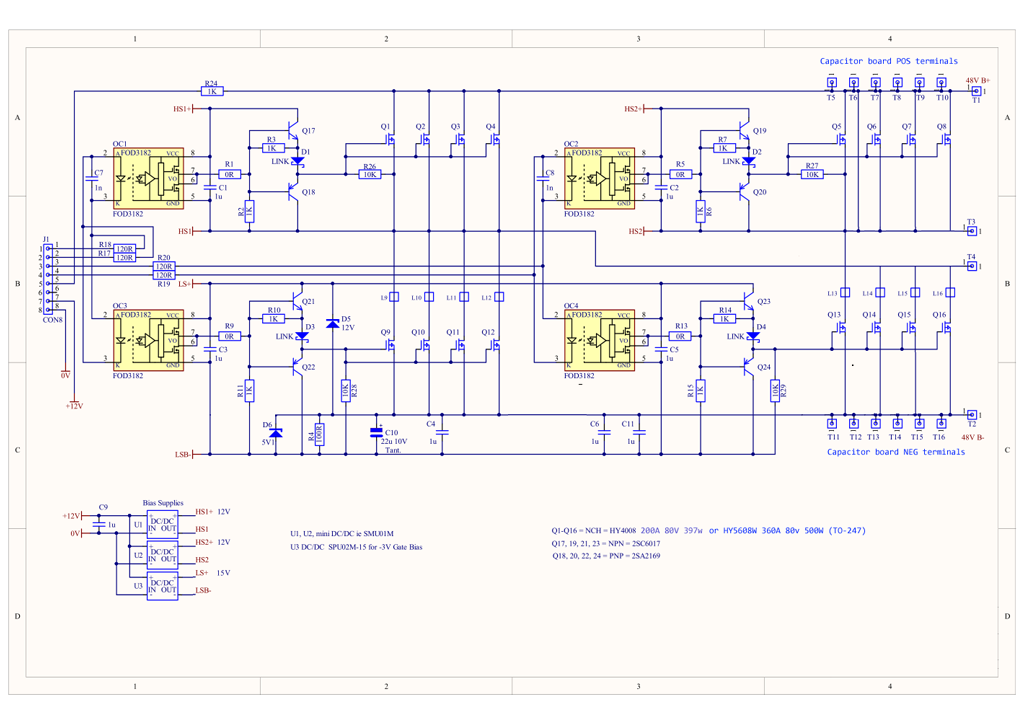
I will provide a detailed circuit and more parts info along the way.
The next few posts will only be on the Power board. The Nano driver board will follow.
This power board is a proven high power running inverter design, you simply select or wind your Toriod and connect.
The board layout, FET mounting and Heatsink mounting is very simple and clean.
Below: The finished power board mounted on an old heatsink, the two small Cap boards removed.
The Capacitor boards simply screw on and off easily. The 3 terminals top and bottom on each side of the main board are the Connection / mounting posts for the Cap boards.
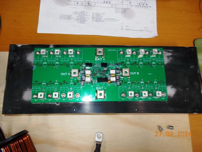
Detailed photos to follow in the next few posts.
NANO Inverter: Full download - Only Hex Ver 8.1Ks