Inverter building using Wiseguys Power board and the Nano drive board


Author Message
KeepIS

Guru

Joined: 13/10/2014
Location: Australia
Posts: 1688
Posted: 12:50am 05 Mar 2024      

The information was posted by Wiseguy and I hope he doesn't mine me posting it here.  

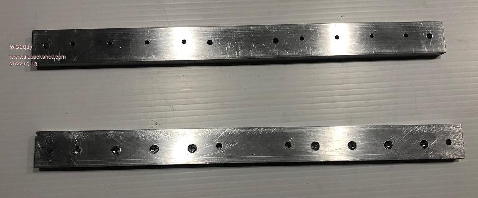
This is the method that he used to avoid tapping 16 x 3mm holes.


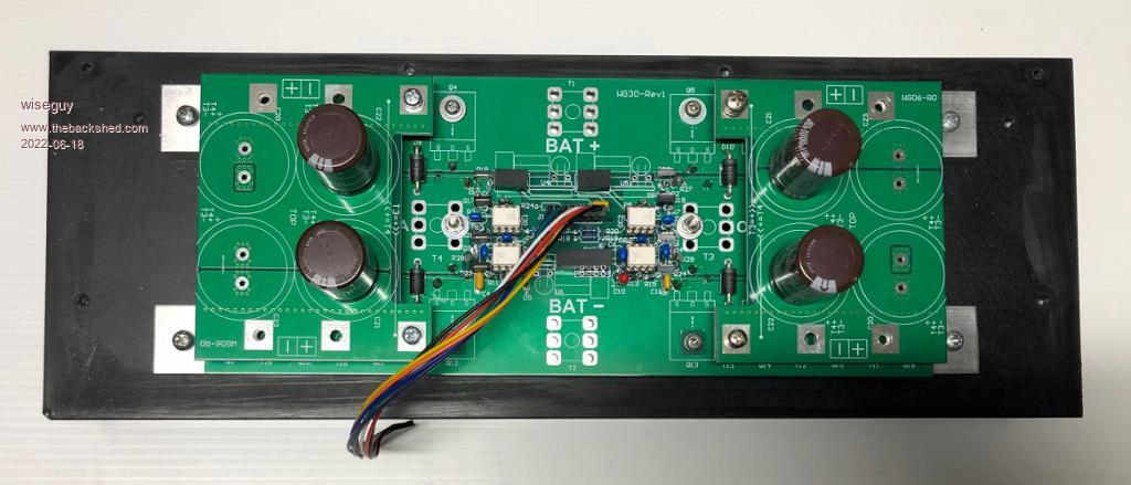
Note the CAP boards are shown in the photo above. There are two types of board, one is for solder in Caps shown above, and another is for screw in Caps.

  Quote   Wiseguy
I mount the Power Mosfets on a 300mm length of aluminum cross section bar 25mm wide, I use 10mm thickness, there is also a 12mm thick extrusion available. The fine scratches that look like I kicked it around the workshop are essentially invisible to the naked eye but look like gouges when looking at the digital photo....

Prior to using the method outlined below, I used to have to drill and then tap the 16 M3 FET mount holes, which was slow and tedious and always at risk of snapping the tap in hole 8 and having to start afresh.

My new method involves drilling an M3 clearance hole right through the bar and then turn the bar over and using the M3 hole to centre the drill, drill a 6mm dia hole that is ~ 5mm deep on the outside edge (~5.5mm at the centre). The M3 nuts I had to hand were ~ 6.1 - 6.15mm at the widest tips of the nut. Now either using a hex head high tensile 3mm screw and alan driver pull the nut into the 6mm hole using the Alan key driver until the nut is seated as far in as it will go.

Alternatively use the drill press to push the nut into the 6mm hole - I recommend putting the nut on a screw wound all the way to the head first and then use the 3mm clearance hole and the 3mm thread of the screw to help keep the nut square to the hole as you press it in, then unscrew the
screw when finished - it works a treat.

Obviously the intention is to use heatsink compound between the mating faces of the heatsink and aluminum bars when finished.