Guru
Joined: 13/10/2014
Location: AustraliaPosts: 1864
| Posted: 01:28am 05 Mar 2024 |
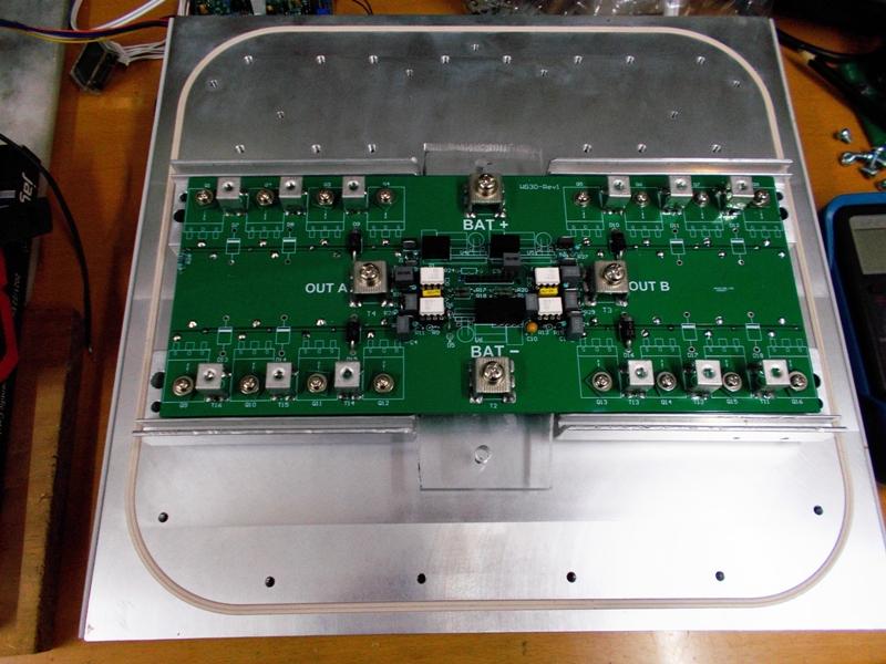
This is the FET Heatsink interface for my big inverter. I made it this way to get maximum heat transfer efficiency.
The Heat transfer bars are cut in half for the Lower bridge FETS, this allows the FETS to be mounted directly to the heat transfer bars without any insulation, giving maximum heat transfer from the FETS under very high power loads and High transient current (heat) demands.
The upper heat bar can be one piece as they share a common +48V rail connection, I used two separate bars as I did not have one long bar. These bars came out of old GT inverters.
Once again there is an insulator mat between the Heat bars and that huge Heatsink. I have found that this heatsink might be a bit of overkill, what you can't see here is the massive fin size area and thickness of that heatsink.
The heat transfer bars present a large surface area to the insulator mat / heatsink interface and ensure maximum efficient heat transfer through the insulator mat into the Heatsink.
In my case the Heat transfer bars are again 3mm tapped.
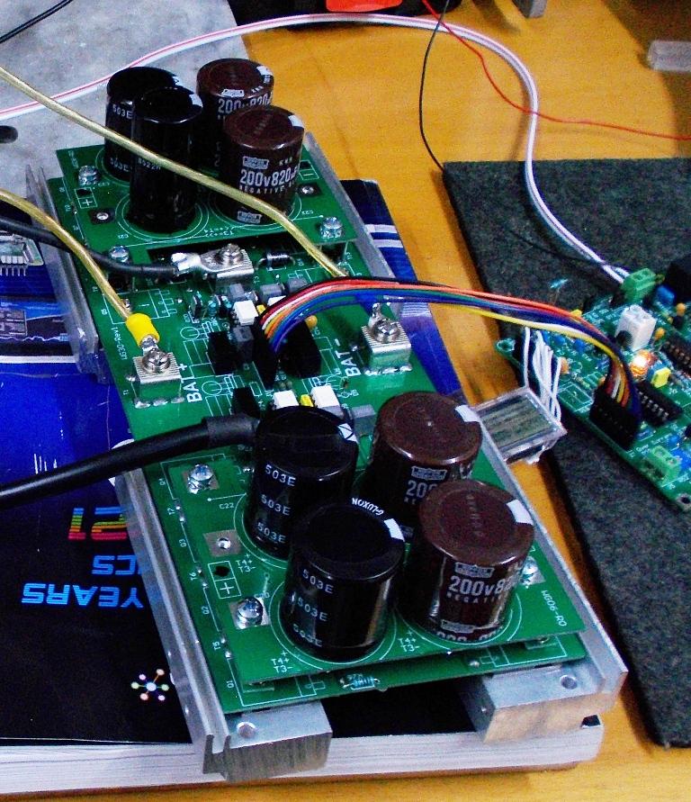
Old pix of a test setup with small value Cap boards.
.
Edited 2024-03-05 11:40 by KeepIS