Guru
Joined: 13/10/2014
Location: AustraliaPosts: 1872
| Posted: 01:12am 06 Mar 2024 |
FET to Heatsink mounting:
The screws for the high side FETs must be insulated from the positive plane with a small TO220 mounting bush. You can also purchase TO220 insulating washers (instead of the Heat mat that I use) and bushes in packs of 10 or 20 for a few dollars in AU.
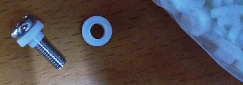
I use a little square fiber pcb washer on top as well, these come as part of each cap board, just need to cut them off.
The lower side screws don't normally need to be insulated as they connect -48v to the heatsink, however in my case I used insulating bushes here as well, so the heatsink is fully insulated from the inverter power planes.
My reasoning is that if something accidentally touches the heatsink, nothing gets shorted out or blown if the heatsink is not mounted to a metal chassis and not connected to anything. But that's just me - do as you please.
There is more spacing between the Gate resistors and the insulating mat that it appears in the photo, optical illusion. Here you can see the screw insulating bush and the square fiber pcb washer on top.
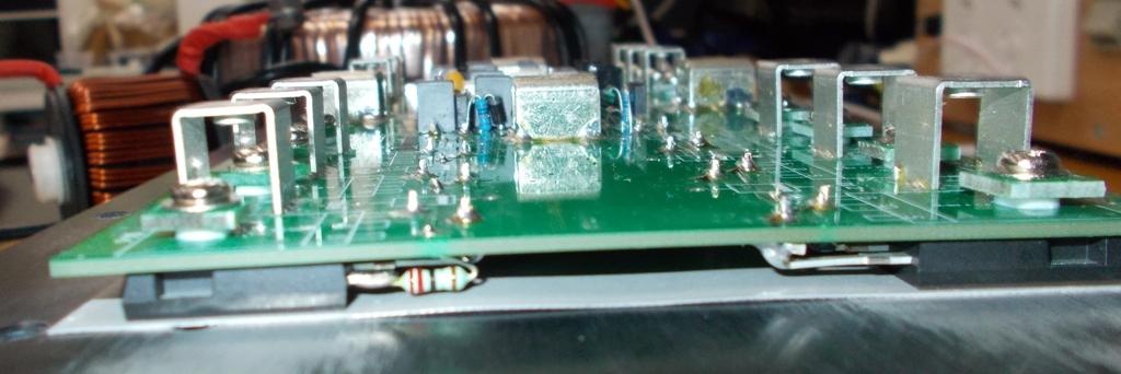
BTW Having the heatsink grounded or floating does not appear to make any difference to the Power board waveforms with respect to noise.