Guru
Joined: 13/10/2014
Location: AustraliaPosts: 1872
| Posted: 04:19am 24 May 2024 |
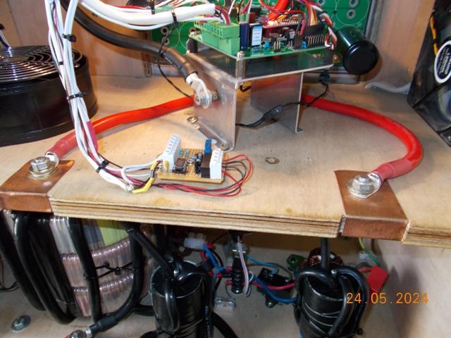
For anyone interested, a picture of the Peak DC current detector in the inverter, it's the small veroboard at the front of the shelf.
Maybe I should ask Klaus if he ever made a PCB for his?
The aluminum stand forms part of a ground plane for the Nano controller.
The Nano board is mounted with a single plated copper post and 3 plastic posts, the metal post connects the aluminum plate to the ground plane mounting terminal built into the controller PCB. It's important to ensure that no other ground connections interfere with this - The PCB ground plane connections is not connected to the controller PCB ground.
This setup makes a huge difference to inverter noise in the Controller board. The aluminum stand is connected by a very short heavy gauge cable to the Negative battery terminal. Terminal is just above the stand.
As inverter noise extends way up in the RF spectrum, this lead must be as short a possible and of good quality thick copper cable. This was setup and confirmed with a 380Mhz bandwidth DSO.
The Red cables either side of the stand run from the Power board SPWM outputs, they connect to two Chokes in the lower Toriod section via copper plates and through bolts.
The Power board at the back of the controller section is seen protruding through a cutout in the rear of the cabinet, the power board is mounted to a huge heatsink and the heatsink and power board are easily removed as a single unit in a few minutes.
FYI the Toriod is 200mm high, each choke is 100mm high.
.
Edited 2024-05-24 17:26 by KeepIS