Guru
Joined: 13/10/2014
Location: AustraliaPosts: 1877
| Posted: 06:10am 24 Jun 2024 |
The choke in the foreground in the previous post was from the PvEdge, it came attached to the toroid, it measured around 1.8 mH which is useless and was not used.
The choke behind it is 43uH, in one side of the spwm drive, this is also too big. I have a 19uh on the other side and complained here a few times about not having any small toriods to make the correct sized 21uH choke.
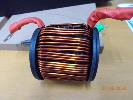
I stripped the PvEdge choke and it had what had I hoped for, 4 large hole toroid rings, a quick guess of 6 turns resulted in 22uH.
The Aerosharp toroid was not happy with a high 43uh combined with a 19uh for a total of 62uh. I have proven in every inverter I have built that a total of around 41uH preforms best with toroid chokes in these inverters.
The exception was standard inverter 8010 spwm drive boards, these only need one choke. The wiseguy symmetrical drive versions and the Nano need two, use a similar value as one choke but the inductance is divided across two chokes.
What a difference:
The idle current dropped from 22W to 14W, the little toroid is now completely silent instead of a slight buzz. So I also scored the choke toroids I needed for the backup inverter.
This is consistent with the inverters I've built, BTW testing an ferrite E-core wound to 22uH did not improve the inverter and created other issues under load.
Quick 6 turn lash up gave 22uH.
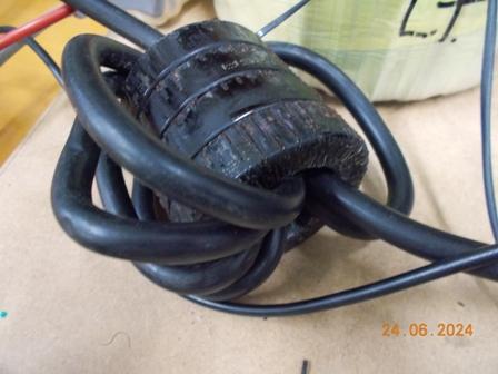
The 43uh choke it replaced (it was all I had at the time)
Edited 2024-06-25 08:05 by KeepIS