Newbie
Joined: 06/02/2024
Location: GermanyPosts: 28
| Posted: 07:09pm 06 May 2024 |
Hi,
Yes, the LED is supplied with 3V3 but I need a TTL signal to feed the signal into my logic.
I solved the issue now with a small level shifter:
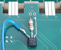
There is a 10k pullup to 5V on the blue line, which is not shown here.
This gives me nice 0/5V signal if the LED is ON/OFF.
Was not as complicated as I thought. :-)
Cheers
Matthias
Newbie
Joined: 06/02/2024
Location: GermanyPosts: 28
| Posted: 04:04pm 07 May 2024 |
Hi,
It seems that my last delivery from JLCPCB was not as spotless as expected.
The last board does not work.
I can program it and everything looks fine but the board does not start up.
5V and 3V3 are there, green LED is on, but that's it.
Any hints where to look at?
I don't think it has something to do with it, but I reprogrammed the board with an older firmware. But putting 2b11 back on doesn't change anything. The board is still dead.
Best Regards
Matthias
Guru
Joined: 11/12/2012
Location: United KingdomPosts: 10240
| Posted: 06:01pm 07 May 2024 |
Try erase all before programming. I've found this necessary on a couple of boards but I don't understand why
Newbie
Joined: 06/02/2024
Location: GermanyPosts: 28
| Posted: 03:09pm 08 May 2024 |
Thanks. I will try this
Matthias
Newbie
Joined: 06/02/2024
Location: GermanyPosts: 28
| Posted: 05:39pm 08 May 2024 |
Thank you very much. Your hint worked. We are back to 5 out of 5

I would never have thought about a full erase. I'm so happy now.

Cheers Matthias
Guru
Joined: 11/12/2012
Location: United KingdomPosts: 10240
| Posted: 07:48am 04 Jul 2024 |
Grogster has also reported some boards not starting up properly and has sent me an example to diagnose.
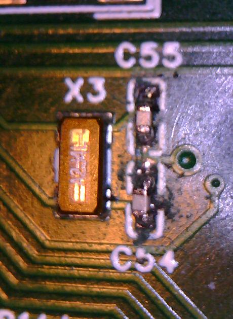
The issue seems to be the RTC crystal circuit.
The crystal is 12.5pf and the two load capacitors C54 and C55 are specced at 10pf
This should give 5pf for the capacitors in series and allow 7pf for the board to give a reasonable match to the crystal.
Perhaps the capacitors supplied by JLC are incorrect? I can’t measure anything that low so no way to test.
I have fixed Grogster's board by simply removing C54 and C55 so if anyone else is having a problem they could try that.
There is an alternative fix with new firmware that clocks the RTC off the main 8MHz oscillator which is more accurate and eliminates the need for the RTC crystal entirely.
HOWEVER, the oscillator doesn’t run when the power is off so the DS3231 has to be enabled to avoid time loss with this firmware.
I can post this firmware if necessary.

Admin Group
Joined: 31/12/2012
Location: New ZealandPosts: 9593
| Posted: 01:21am 08 Jul 2024 |
Yes, I had three boards that would not start from my last batch.
Following Peter's advise after he played with the board I sent him, I simply removed C54 and C55 from the other two boards I had here that would not start, then they started up just fine.

Standard firmware.
I will most likely simply leave these caps off the BOM for the next batch of boards, or substitute a lower value that Peter suggested to me during our emails.
But so far three out of three boards that would not start, started just fine if you remove the two load caps, so I will probably get at least some boards made with those caps simply left off and see how we go.


Regular Member
Joined: 03/11/2020
Location: GermanyPosts: 99
| Posted: 02:44pm 08 Jul 2024 |
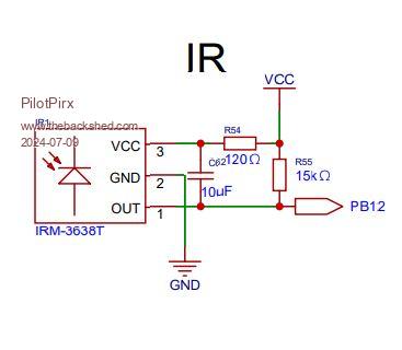
The IR receiver does not work on my board. When signals are received, they look like a capacitor charge/discharge curve. In the circuit diagram it looks like there is a 10µF capacitor on the signal output. This cannot be correct. I assume this is to buffer the supply voltage. Has anyone tested this? Is there an error in the circuit diagram?
Guru
Joined: 11/02/2018
Location: AustraliaPosts: 2611
| Posted: 09:39pm 08 Jul 2024 |
Yes, remove the capacitor and solder it between pins 2 & 3 on the underside of the board.
Guru
Joined: 11/12/2012
Location: United KingdomPosts: 10240
| Posted: 07:37am 10 Jul 2024 |
Apologies for the IR circuit bug. Attached V2.1 gerbers/BOM/PLC and schematic
NB: I've also changed the load capacitors for the RTC crystal to 6.8pf
Gerber_PCB1_2024-07-10.zip
BOM-PLC-SCH.zip
Newbie
Joined: 17/04/2024
Location: United StatesPosts: 2
| Posted: 12:21pm 10 Jul 2024 |
As a note, after removing C54 and C55 from the two boards I had allowed them to boot as well. Thanks for the update.
Admin Group
Joined: 31/12/2012
Location: New ZealandPosts: 9593
| Posted: 01:40am 15 Jul 2024 |
Good to know.
The next batch of boards I get made, will use the updated PCB layout and components as posted by Peter above.
Guru
Joined: 11/12/2012
Location: United KingdomPosts: 10240
| Posted: 09:44am 24 Jul 2024 |
For reference, I managed to install 6.8pF capacitors on the board Grogster sent me that failed with the (supposed) 10pF capacitors and the board works fine. So hopefully the revised BOM posted above will build working boards without needing to mod anything.
Tricky bit of soldering with 0402 parts
Guru
Joined: 05/10/2019
Location: United KingdomPosts: 7865
| Posted: 10:00am 24 Jul 2024 |
I wouldn't have thought that layout would have caused problems with caps. A guard ring round the crystal and caps might have helped, but even then I'm not sure. It depends on what other signals are around. Ideally the capacitor junction should go directly to the closest CPU GND pin to the crystal connections.
Guru
Joined: 11/12/2012
Location: United KingdomPosts: 10240
| Posted: 11:13am 24 Jul 2024 |
4-layer board so there is a full GND plane directly under the crystal and caps. The via between the caps connects directly to it. This layout has been used many times without issues that is why I'm suspicious of the original caps supplied by JLC. I've got no way of testing caps in the low pF range so can't prove my suspicions
Guru
Joined: 05/03/2018
Location: NetherlandsPosts: 5058
| Posted: 11:33am 24 Jul 2024 |
Hi Peter,
For testing low pF capacitors, build the LC meter.
About crystals. Crystals where typically made from crystal, a glass type that contains lead. Since lead has become more and more banned, the applications where lead is tolerated have become less. So in recent time (last 5-10 years) crystal manufacturers have searched for alternate materials, not containing lead.
They have found such materials, but these materials are not capable of handling the same amount of enery. Therefore modern crystals have a lower drive strength, and higher ESR that the classical lead based crystals.
Some "older" chips do not have the required gear box in the crystal oscillator circuit to change the gain, and drive strength, to meet these requirements. It is possible that (unintended by either you or JLC) modern parts are used. And by lowering from 10p to 6.8p you compensate for the higher losses in the modern crystal. In changing these capacitors, you will off-tune the crystal slightly, but as long as the VGA monitor locks, that should be not an issue.
The STM32H7xx series is not that old, it could have register to adapt the oscillator gain and drive strength...
Regards,
Volhout
Edited 2024-07-24 21:34 by Volhout
Admin Group
Joined: 31/12/2012
Location: New ZealandPosts: 9593
| Posted: 11:11pm 25 Jul 2024 |
My next batch of boards with the IR and X3 fixes should be here any day now, so I will let the thread know if any of them don't start. This batch will be fitted with 6.8pF caps as changed by Peter.
0402 is getting a bit small to hand-solder, even for me!

Heating them up and removing them is no real pain, but as for soldering on new ones...
Well done, Peter!
Guru
Joined: 31/03/2022
Location: United StatesPosts: 463
| Posted: 07:02am 26 Jul 2024 |
I just deleted a LONG Rant about the E.U., Executive Summery I'm an American, A Texan, and those Sissy Marys will take my Radio and CPU Crystals from My Cold Dead Hand ! just like the STUPID E.U. Ban on Chrome I hope to god one of them tries to stop me from Chrome Plating parts
Guru
Joined: 05/03/2018
Location: NetherlandsPosts: 5058
| Posted: 08:01am 26 Jul 2024 |
Rickard5,
You are very aware of the risks that Lead presents for humans when it ends up in the environment. And similar for Chrome. However, at the moment the politicians that define the laws have set out generic rules roadmap.
Specific for crystal (the glass, not the oscillator part), when that ends up in a landfill, the sun will be a red giant before the lead is freed from the glass. So it will never end up in the ground water. So (specific for lead in crystal) the law is too strict. B.t.w. the law is about Lead content (weight) percentage of the total weight of the part. Actually ppm in weight.
Since a modern oscillator crystal weight is in miligrams, you have to start counting lead molecules in the crystal glass....
Volhout
Guru
Joined: 05/10/2019
Location: United KingdomPosts: 7865
| Posted: 08:11am 26 Jul 2024 |
I'm sure I've seen resistors fitted in series with crystals in some cases. I can't remember details though.