Admin Group
Joined: 31/12/2012
Location: New ZealandPosts: 9593
| Posted: 02:46am 18 Apr 2024 |
THIS one has me totally confused.
I designed a PCB to use a 9341 SPI LCD coupled to a 170 MM2 chip, and that board worked fine - so did the LCD.
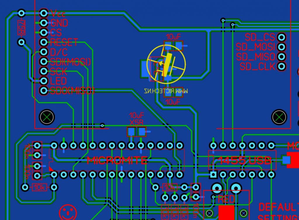
I then redesigned the board to allow for an extra button, BUT the layout to the LCD remained EXACTLY the same as the old board, but the LCD won't work in the new PCB.
All I get, is a bright-white LCD, but it never seems to initalize.
If I take the LCD and the MM2 chip, and plop them back in the OLD board, everything works just fine.
Now, I know what most of you are already thinking at this point - the PCB is bad or has a disconnection on one of the tracks between the LCD and the MM2 chip.
NO, IT DOES NOT!
I have traced out all lines between the LCD and the MM2 chip, DIRECTLY on top of the LCD, and on the top of the pins of the MM2, so that this also tests the connections in the sockets for the LCD, and also the IC socket for the MM2 chip - ALL signal lines are intact, and zero ohms. None are a high resistance or anything like that, they are ALL there, where they should be.
I tried a couple of different LCD modules on the NEW board - they WON'T work, but they WILL work in the old board.
I'm out of ideas at this point, as it does not seem to be the LCD, the MM2 chip, the PCB tracks OR the connectors for the LCD and the socket for the MM2.
Electrically, it traces out as exactly the same as the one that DOES work, but it will NOT work on the new board.
I'm now left scratching my head, as I cannot work out what the hell is going on here.....

Here is an image of the relevant part of the PCB layout:

OPTION LCDPANEL ILI9341, RLANDSCAPE, 26, 24
MMBASIC ver 5.05.01
About the only thing I can now think of to test, is that we have one or more lines between the MM2 chip and the LCD, that are shorted to ground(or each other) or something, so I will test for that next.
There HAS to be a reason.....

Smoke makes things work. When the smoke gets out, it stops!