Guru
Joined: 11/12/2012
Location: United KingdomPosts: 10240
| Posted: 11:43am 01 Feb 2025 |
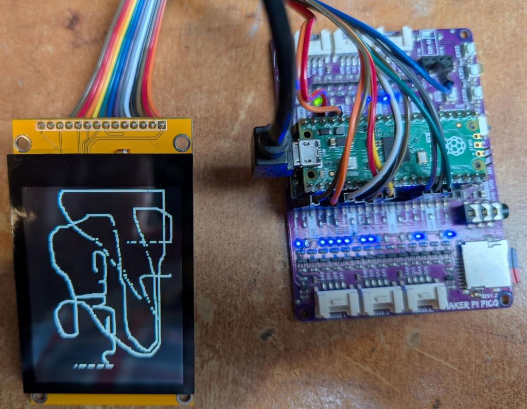
PicoMite V6.00.02b6 now supports capacitive touch using the FT6336 chip.
In theory this chip supports touch reporting of up to 2 points at once AND simple gesture control.
There are lots of boards with the chip available from the usual places
I bought a couple as they look to have great potential with the PicoMite.
The display itself is an IPS 320x240 controlled by the ILI9341 chip and this works nicely (It does need the INVERT option on the setup). In theory there is a SDcard socket but on my boards various of the required pins are not connected so that is useless. The FT6336 works and the firmware does support dual touch however touch seems very laggy. Gesture controls do not work and google reveals the manufacturer of the chip has produced versions both with and without this facility.
Overall, the module is disappointing. I suspect the reason they are available cheap is that a large batch were produced with a wiring error on the PCB (no SDcard connections) and sub standard FT6336 chips.
If you just need a bright display with touch they are OK but no real advantage over the standard ILI9341 with resistive touch.
Guru
Joined: 11/02/2018
Location: AustraliaPosts: 2611
| Posted: 12:12pm 01 Feb 2025 |
Re the SD connections, looking at a magnified image of the back I think the 3 SD SPI pins may be paralleled with the LCD SPI pins.
At the touch end of the connector there appears to be the SD_CS pin.
Check continuity from SD socket to SPI and SD_CS pin to see if this is the case.
Guru
Joined: 11/12/2012
Location: United KingdomPosts: 10240
| Posted: 12:14pm 01 Feb 2025 |
Don't you think I did that?
Guru
Joined: 11/02/2018
Location: AustraliaPosts: 2611
| Posted: 12:30pm 01 Feb 2025 |
The missing tracks could be replaced with wires from the SD socket running through a corner mounting hole to the top side and soldered to the relevant pins.
Guru
Joined: 11/12/2012
Location: United KingdomPosts: 10240
| Posted: 12:37pm 01 Feb 2025 |
Yes, of course but that defeats the object of buying a module
SCK - not connected
MOSI - not connected
SD_CS - not connected
Power, GND and MISO seem OK but as I said - probably duff board being sold off

Guru
Joined: 07/08/2016
Location: United StatesPosts: 593
| Posted: 03:22pm 01 Feb 2025 |
Check out the " version 3.8" version
Quazee137
Guru
Joined: 11/12/2012
Location: United KingdomPosts: 10240
| Posted: 03:27pm 01 Feb 2025 |
Its going to be the same. On further inspection the issue is that they are designed for 5V and have a LCV245 buffer in the signals and, as been proved repeatedly, the SDcard won't work on a Pico through a level convertor. We need a straight connection.
Guru
Joined: 25/06/2022
Location: United KingdomPosts: 2540
| Posted: 04:04pm 01 Feb 2025 |
is 2350 pico 2 gpio 5V logic tolerable, inputs ?
output will be 3.3V?
Guru
Joined: 11/12/2012
Location: United KingdomPosts: 10240
| Posted: 04:53pm 01 Feb 2025 |
Tried - doesn't work. SDcard with buffers just never work with the Pico
Guru
Joined: 07/11/2023
Location: United KingdomPosts: 1360
| Posted: 12:46am 02 Feb 2025 |
Not totally discouraged because I don't have a need for SDcard.
But "laggy" when streaming or is there a perceptible lag when point touching?
Senior Member
Joined: 08/06/2022
Location: AustriaPosts: 220
| Posted: 07:54pm 04 Mar 2025 |
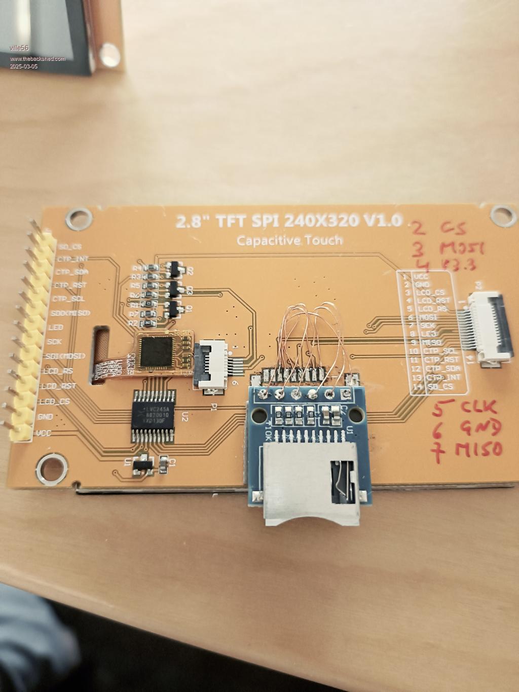
Just rewired the SD card connector correctly. The original wiring was rather weired, to be honest .... no idea what is should have been used for.
Removed the original connector completely and used a micro SD breakout board instead. Now the SD card is connected via the on board 74LVC245A and it works like a charm. So this type of level shifter (LVC245) seems to be compatible with the pico.
Guru
Joined: 20/09/2024
Location: GermanyPosts: 491
| Posted: 08:58pm 04 Mar 2025 |
I don't understand how the dir input is controlled.
Guru
Joined: 11/02/2018
Location: AustraliaPosts: 2611
| Posted: 09:39pm 04 Mar 2025 |
Just a guess, would connecting DIR to the SPI clock work?
My reason for thinking it might work.
Edited 2025-03-05 09:19 by phil99
Senior Member
Joined: 08/06/2022
Location: AustriaPosts: 220
| Posted: 09:07am 05 Mar 2025 |
the DIR input of the LVC245 is not controlled at all, it is fixed to one direction, just tied to Vcc. The trick is that only signals going FROM the pico to the display/SD/CTP are level shifted. Signals from the display/SD/CTP TO the pico are left unchanged. So there is no need to control DIR pin. As the Display, CTP and the SD card are running with 3.3V this is no problem for the pico.
The touch chip has an additional level shifter composed of 2 MOSFET for the I2C SDA and CLK and only uses the LVC245 for the RESET signal. For the SDA signal the MOSFET is necessary as this signal is bidirectional. Again, the CTP IRQ signal to the pico is not level shifted.
Attached is the schematic diagram I am using ....
2.8inch_SPI_Module_MSP2833_MSP2834_Schematic.pdf
Gerald
Guru
Joined: 20/09/2024
Location: GermanyPosts: 491
| Posted: 09:49am 05 Mar 2025 |
Thanks for sharing. Do I get that right, SPI MiSo of sd and tft are tied togethter on the board?
How long are the wires you connect it with?
Edited 2025-03-05 19:55 by dddns
Senior Member
Joined: 08/06/2022
Location: AustriaPosts: 220
| Posted: 11:54am 05 Mar 2025 |
yes, tied together.
As of the schematics every signal name beginning with 3V3 is level shifted. The MISO signal ist named TFT_SDO in the schematics and thus
a) not shifted and
b) the same for the TFT screen and the SD card.
The wires I use are about 3cm long and is a VERO-pen wire. This wire is about 0.1 mm in diameter and has the advantage that the insulation melts away with soldering iron temperatures. Normal magnet wire is a PITA to get the insulation off. Soldering to the SMD pads on the board was no problem, I did not even change to the SMD soldering tip.
Guru
Joined: 20/09/2024
Location: GermanyPosts: 491
| Posted: 12:28pm 05 Mar 2025 |
Thanks and sorry for not precise phrasing. I was interested in the length from header14 to the pico. Anyway, daisy chaining on SPI never worked for me only for very short connection lengths of traces or wires.
Guru
Joined: 20/09/2024
Location: GermanyPosts: 491
| Posted: 01:16pm 05 Mar 2025 |
Found these docs, some are in english.
This is IPS and thus worth the research. But the issue how the layout is done won't go I guess.
Senior Member
Joined: 08/06/2022
Location: AustriaPosts: 220
| Posted: 02:39pm 05 Mar 2025 |
- I'm using flat ribbon cable with 15cm length without any issues (plus the additional 3 cm for SD card now), the type which is available from many sources for almost no money.
- the docs you found seem to refer to a different type/brand of board. The layout is different for sure and probably correct for the SD card part. The one I'm using has a distinct yellow color for the silk screen whereas yours is black. Both are IPS though. This is the reason why I was trying to get the SD card working. A TFT display would have been not worth the effort, at least for me.
Guru
Joined: 20/09/2024
Location: GermanyPosts: 491
| Posted: 03:07pm 05 Mar 2025 |
I think you can be lucky.
I would tear off sdslot and levelshifter and anything, which touches SPI from the TFT.
You can have the SD stuck to the display, but it should be wired separately to the MCU...IMHO
Edited 2025-03-06 01:18 by dddns