
Newbie
Joined: 22/11/2009
Location: United StatesPosts: 27
| Posted: 08:42pm 27 Nov 2009 |
davef,
Thanks for your helpful remarks. I'll check out RFSim99.
Steve,
Here are the circuit photos you requested. The first one shows the complete bread board, as follows:
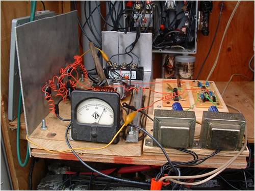
The +/- 12 volt power supply is shown in the front right; Mosfets and their heat sink plate (8"x12") are shown on the extreme left; bridge rectifier, back left, circuit boards, back right. The DC ammeter is reading about 14 amps.
The coil is shown here:
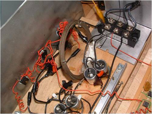
As stated in Figure 1, the coil is made from two parallel strands of 14 awg magnet wire, 10 turns wound into a 4" diameter coil potted in JB Weld.
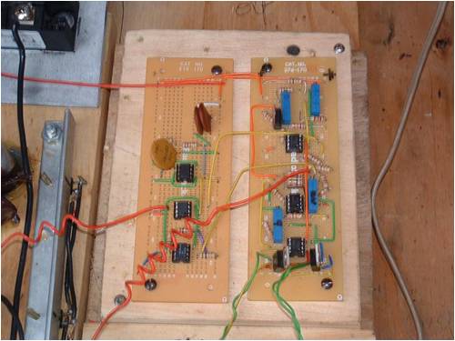
The circuit boards are shown here:
The next step is to package the components in an enclosure and mount it on the wall of the control shack.
Blessings and peace.
Bob Shaubach
BobS