
Guru
Joined: 15/07/2006
Location: AustraliaPosts: 676
| Posted: 11:10am 05 Jan 2011 |
Well it has been a long time in the planning, to build an AXFX. In fact I bought magnets something like a year ago.
I had sketched many and varied ways of constructing an AXFX, tossing up whether to start fresh or use existing parts I make. I even contemplated and sketched how to use a trailer hub/axle assembly. The only way to make it real good was to start fresh, make everything to suit, but limited on time, I wanted to cheat every corner I could.
The decision eventually was to make an AXFX into the existing White Pointer 2.9. In fact both White Pointers are exactly the same except the blades and cone. But in this AXFX application I will use the 2.9 diameter blades as the starting point.
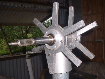
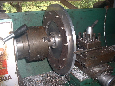
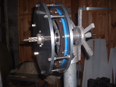
Here is the internals of the White Pointer with a F&P standard shaft and a keyway cut in to drive the AXFX.
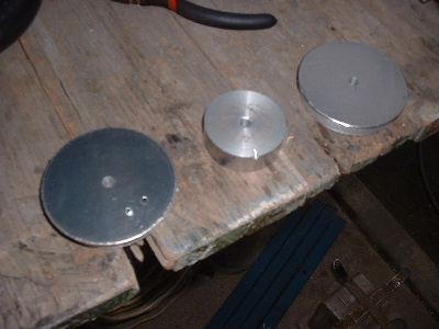
I really don't like rust and so steel, the necessary part, is kept to bare minimum. Also hoping to keep the weight down, but turns out that I only saved a few kilograms. Considering all the extra work, its probably not worth worrying about. Alloy and steel amalgamated.
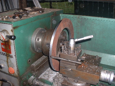
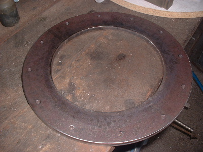
Then painting the back of the steel.
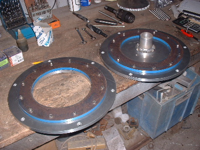
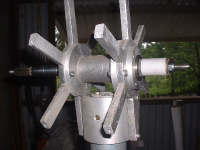
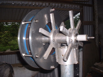
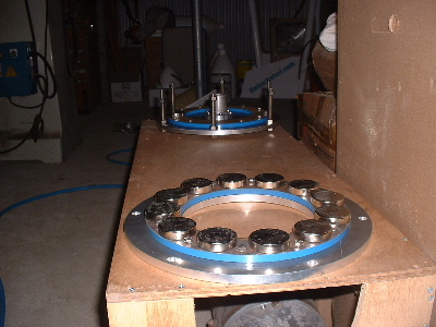
Assemble the hardware to see how it look on the White Pointer base parts.
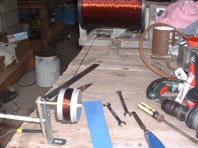
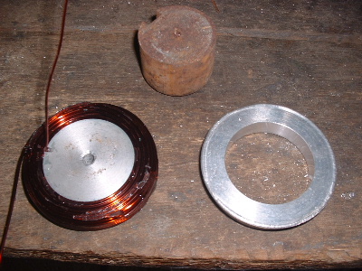
Time to make a wire winder and wind some coils. I have made each coil 100 turns of 1.25mm2. This is the same wire I supplied to Glenn and so I based some guess work on his test coil of 10 turns. I would like to have put more turns in but I had no more space to the 12mm threaded rod that holds the 2 magnet plates apart, or together, whichever way you look at it.
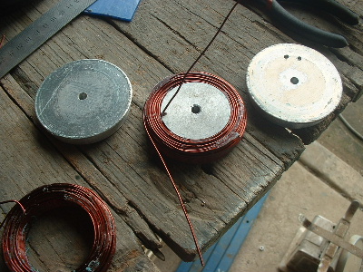
The coil winder is in 3 main parts. It has a disk on each side with a centre piece machined to 48mm diameter x 16mm wide. The handle is a pen outer casing over a piece of thread bar! I used PVA (F/glass release) on the wire winder so the araldite will release. Araldite is used to hold the coil together. The sides came away easily, but the centre I hit it out over a machined ring the right diameter.
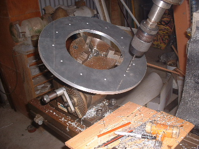
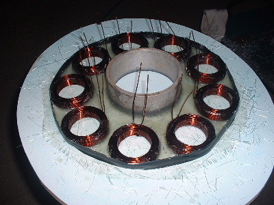
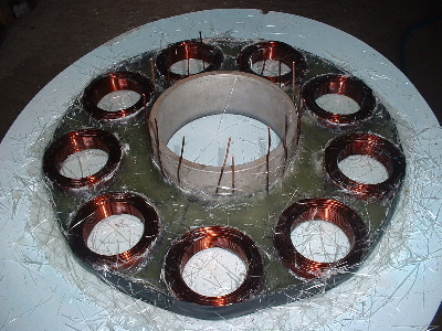
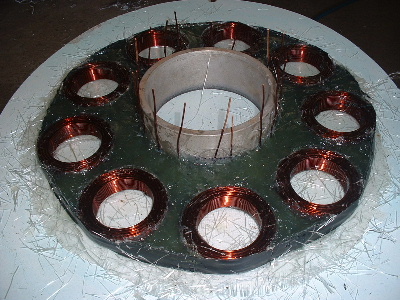
Making up the stator is not as easy as it looks. I could have made up a special mould but always looking for a short cut, I decided to draw the layout on the laminated board. With the centre ring in place and 1 layer of 225 woven glass matt around it, the lines can still be seen on the board. With it wet, I placed all the coils and left it to set. When set, I put on the insulation tape around the edge. 1 coil came loose, so sat a weight on it and wet in some Chopped Strand Matt (CSM). I used polyester resin so could not fill it up all in one go. No good as a casting resin. Laying the CSM and woven rovings in first and then wetting out with resin was a real pain, leaving lots of spikes up around the coils and edges, they just would not go down. After the first layer the edges started to lift from the board, so I had to hold it down with weights. For the last section to fill, I chopped up some CSM into very small pieces and mixed into the resin. In the right ratio it worked a treat. That was so much easier to put in.
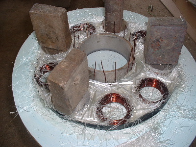
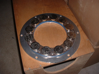
Started to fit the magnets. Tough little fella's they are. Showing signs of moisture in contact from the thin ply wood that was between them.
Edit: to put a space between the pictures
Trev @ drivebynature.com