
Guru
Joined: 22/02/2006
Location: AustraliaPosts: 1435
| Posted: 03:56am 04 Aug 2011 |
Part 2
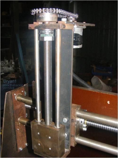
This is the Z-axis which I made from scratch. The lead screw is a 12 tpi acme thread I cut in my toolroom lathe and I have an acme tap to suit. The thread is very little to no backlash. The 2 guide bars are 10mm rods taken from an old printer so they are good hardened rods. The cutter head block is also cast iron and I tapped 4 off 6mm holes so the cutter head can attach.
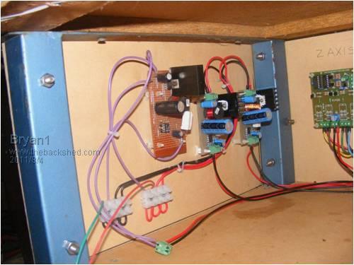
This pic shows the 3 seperate 3 amp constant current circuits, one for each axis. The veroboard one was given to me by the guys at the Adelaide Uni and I made circuit boards for the other 2. They work very well and I reckon 3 amps is more than enough current for the steppers I'm using.
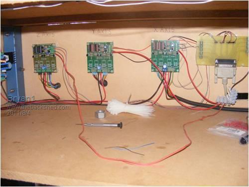
This the control section with 3 off of the Oatley controllers and the parallel input board I made my self ages ago for early testing.
For ages I played around with acme screws then all thread but gave up in the end and bought ball screws for the X and Y axis's. It was the best move I made as they run silky smooth even single stepping. With a 5mm lead they will really suit a micro stepping setup and I will get working on them pretty soon. For now I'm goingto setup my dremmel tool and just use the holder off the dremmel drill base to get me going.
All in all this is around 4 years work off an on and if I didn't break my finger and have the time off this project would still of been 6 months away.
The first job will be machining a grid pattern on the fibre board base and drilling some M6 holes 18mm deep so not to break thru to be used for holding down jobs. I still need to instal the limit switch's and make up the main control board with the power switich's and the E stop.
Cheers Bryan