
Guru
Joined: 22/02/2006
Location: AustraliaPosts: 1450
| Posted: 08:29pm 09 Dec 2013 |
G'day Guy's,
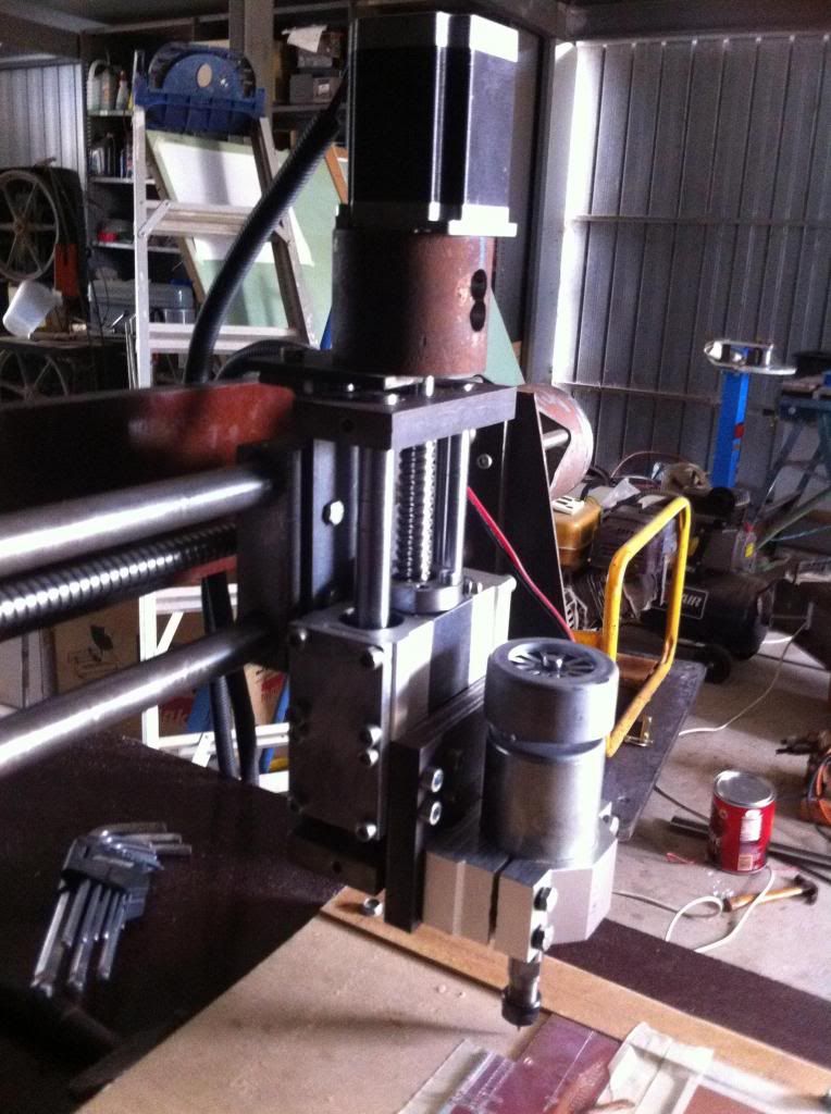
Well I did make a new Z axis but found using just single linear bearings they was a bit of slop on the cutter so decide to grab 4 16mm linear bearings off ebay and make a whole new Z axis. In order to hold the ball screw nut I machined up 2 identical steel blanks to sit on the inner of the linear bearing holder then tapped a hole in each to hold the nut. A 6mm ali plate holds each pair together and a 15mm plate hold the DC motor spindle.
Now to test out the CNC I put some pcb on the bed and did a few trial runs to get the right depth. Decided to finish the pcb design of the arduino LCD board so I can use it on the DM. Anyway I've been using Sprint Layout for years to do pcb design and feel it is great for PCB design BUT NO BLOODY GOOD for gerber export. I used that scrap piece to do a dummy run to ensure the Gcode was right only to find on cutting the pads they were cut alround and when a track was cut EVERY BEND was cut individual. So back to Sprint Layout and try using the 'connections' button so every pad and track were identified.
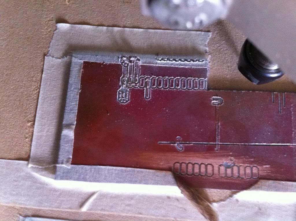
Nope that didn't work and the crap in the middle was the result. So after watching nearly 2 hours of dave's EEVblog on Kicad I downloaded that to try. What a nightmare to try and use so next stop will be designspark and see if that is a tad easier to use.
Regards Bryan