Guru
Joined: 02/02/2017
Location: AustraliaPosts: 1432
| Posted: 12:59am 10 Mar 2017 |
Warpspeed:
of course the best way to go is to drive the clock input yourself. Hardware locked PLL would be the best. But I like hacking up something to have a play.
Part 3: Output waveform wiggles
We all must have seen the AC output wiggles and wondered where it comes from.
These wiggles take different forms depending on the builder and his choice of transformer primary windings, AC output capacitors and inductors. Other factors can effect this too.
It's important for this discussion to accept that the circuit we have in our inverters is
an LC tank that resonates when given any reason to do so. It has some dampening which permits out inverters to function fine (or not). It's actually a LCR series thing but it behaves like an LC tank.
The circuit is driven by the mosfet bridge, then one wire has an inductor in series, then the primary winding (with additional inductance) then back to the other bridge output. There is a capacitor connected in parallel with one or more inductances.
There is some series resistance from the primary winding wire, primary inductor wire etc.
This helps dampen the oscillations.
I think I have found the cause of these wobbles in the AC output waveform.
First some examples of mine:
13 turns on the Aerosharp output choke (not very large but they ARE there.)
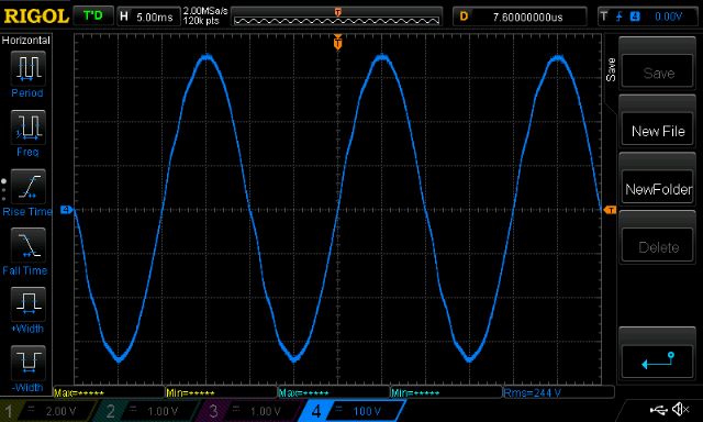
8 turns of thicker wire on same choke (still there..)
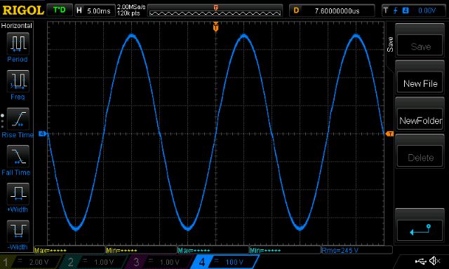
3 1/2 turns on a TDK E core "E 65/32/27" as used by Oztules and others.
I wonder why it is asymmetrical?
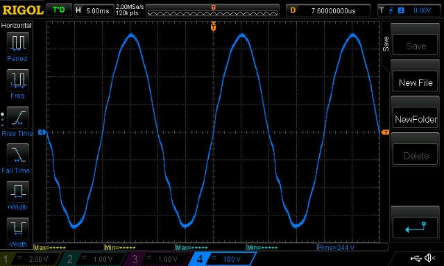
In all cases you can see wiggles in the sine wave immediately as it passes zero.
These wiggles reduce to nothing about at the top or bottom of the waveform.
My oscilloscope can perform math on a waveform, so I show a high pass filtered trace (purple) of the output AC alongside the original AC waveform. High pass filter removes the 50Hz part of the waveform.
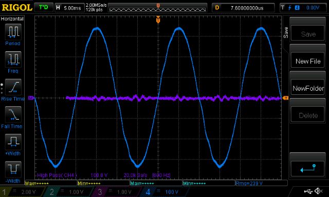
We need to shift the filtered trace leftwards about 1 division to line up with the source. Notice there is some oscillation that is damped and dies out after a few cycles.
We all have had this to some degree. Sometimes the oscillations are damped out really quickly and so we see just a step up/down as the AC output passes zero.
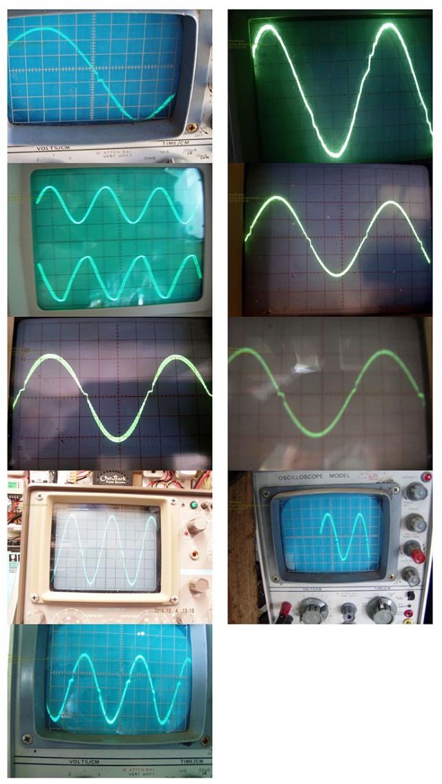
(let's play spot my CRO trace...)
Anyway, all that is just my view.
I modeled a PWM sinewave driving the same LC tank circuit and you would not believe what I saw.
If you have access to Multisim v.11 you can download the circuit below.
Here is the PWM output alongside the sinewave that is modulating the PWM.
Red is sinewave modulation for PWM, yellow is LC filtered PWM output which is supposed to represent the AC output waveform from an inverter.
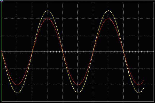
You can clearly see the wiggles appear after each zero crossing. They die out after a few wobbles.
The simulation lets me modulate the PWM with any waveform.
I tried a square wave.
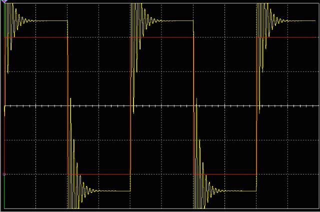
When I saw this, I finally understood the consequences of connecting an LC tank circuit to the output of the mosfet bridge.
It will oscillate, the only question is how much damping there will be, how strongly the oscillations will be excited and the amplitude and frequency.
The simulation employs a 20KHz PWM, output into a 130uH and 50uF LC tank.
These values are close to the sort of values we use in our inverters.
The simple "step" immediately after each zero crossing can be seen in some people's devices. This is an oscillation, but it is a highly damped one. It dies out after 1 half cycle or so.
It's cause is the same, only it's effected by different L,C and R parameters.
So, that's that. The mystery to my mind is solved.
It's something we live with if we want to run the inverter at the bleeding edge of efficiency with massive primary windings, little primary inductance and a decent AC output capacitor. It will oscillate and that's that.
Some people think these steps and oscillations are due to imperfect PWM modulation by the EG8010 around the zero crossing. At the time a little before, during and a little after the zero crossing, the PWM must be off completely to deliver zero volts to the primary. Then the first pulse of PWM that is trying to generate a small increase in voltage (from zero) is seen by the tank circuit as a highly energetic single and short squarewave. This makes the circuit ring like a bell.
I do not think these wigggles are the direct result of insufficently correct PWM.
It's what you get from hitting a LC tank with a hammer.
I look forward to any discussion on this topic.
2017-03-10_110432_bipolar_SPWM_shows_oscillation.ms11.zip
wronger than a phone book full of wrong phone numbers