Guru
Joined: 02/02/2017
Location: AustraliaPosts: 1432
| Posted: 05:11am 18 Mar 2018 |
Part 18: primary current during transients
This is just a short note to show what happens to primary winding current when I switch on my test load (167W incandescent globes at 235V AC)
DC supply is 27.5V
I measure aprox. 14.8 Amp RMS in the primary which runs at 12.9V AC
14.8 x 12.9 = 190W. Near enough.
I record primary current this time with a current transformer and 100R shunt resistor.
It calibrates to about 0.095V / Amp
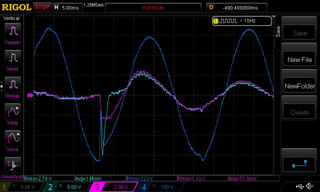
Here is the switch on event
Light Blue is current transformer
Pink is LEM current sensor
Dark Blue is AC output

That peak is 15V on the CT which is about 158 Amps
The LEM current sensor saturates the output at about 2.5V which is 59 Amps
So we see a switch-on transient of 158 A when a 167W load is switched in but when
steady state, it needs only 21 Amps peak.
Imagine the kinds of peak primary current when Oz torture tests his inverters with the welder..
Or we turn on inverter driven motors in the split system A.C.
I wonder if having just a little primary winding resistance is a good thing.
wronger than a phone book full of wrong phone numbers