Guru
Joined: 02/02/2017
Location: AustraliaPosts: 1432
| Posted: 10:35pm 12 Feb 2021 |
we have a way / circuit to bypass EG8010 and use
Chinese low voltage hardware with arduino and sketch nano1?
I assume you need drivers like the ir2110 or similar present on the EG8010 and something that emulates the protections offered by the opamps.
I would like to be able to test the sketch with as little hardware as possible
on Chinese inverter.
yes, here is how I do it.
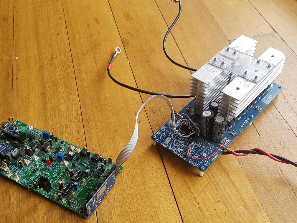
I used a cheap bare PCB I obtained from the supplier and built the minimum,
being DC bulk capacitors, MOSFETS, gate drive resistors and diodes.
Nothing else at all.
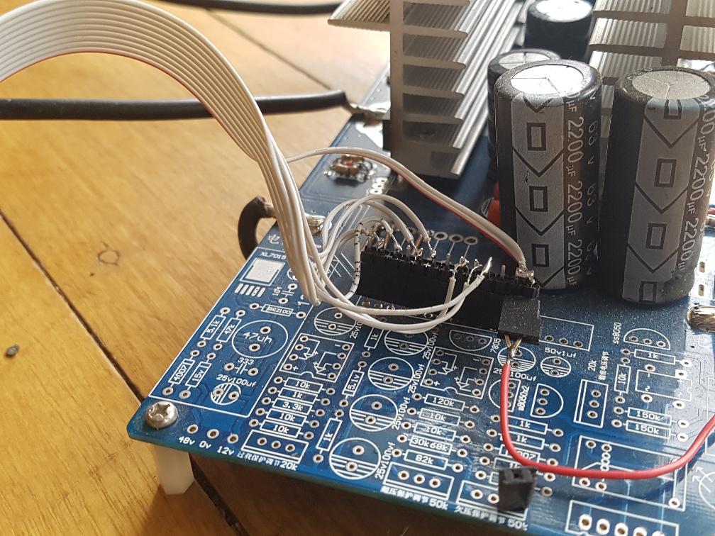
The ribbon cable needs to connect
1LO, 1HI, 1VS, 2LO, 2HI, 2VS, DC ground, DC supply (48V in my case)
into the nanoverter 10 pin socket.
The inverter board is designed for the EG002 module and the pinout is
seen on the back of the module PCB.
I do not have any over current protection present.
The ribbon cable has long conductors that pick up and carry a lot of EMI
to both the MOSFET gates as well as back to the IR2148 driver ICs
This is not a well designed system. But it is outstanding in the ease of building, cost, and experimentation in my view.
This is a low frequency inverter, and so it requires a correctly sized inductor
in series with the primary winding of the output transformer. AC voltage feedback
is connected to the nanoverter.
You can build the bare bones version of the nanoverter. This is the prototype
I made to prove concepts prior to nanoverter design.
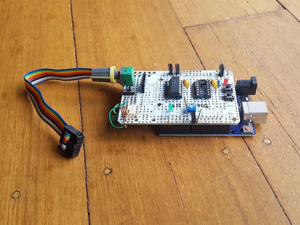
It has only one IR21488 installed but you can see it's not very big. It sits on top of an Arduino Uno.
This board was used to develop most of the code including the mains synchronisation.
It also can and will run the above inverter power board.
You could build a similar small PCB for the gate drive and connect it to the Blue Pill, and then experiment away.