Guru
Joined: 02/02/2017
Location: AustraliaPosts: 1432
| Posted: 12:05am 13 Feb 2021 |
i am trying to figure out how to correct the inverter output shape.
this without relying only on the voltage peak dictated by the feedback to follow the output voltage on both half-waves (I imagine a half-wave on unipolar EG8010)
the idea is to sample the output waveform and compare each sample to the one present in array l[NPWM at the same time of reading.
the difference between the comparison gives the value to be given in
the OCR1A when it will create the output PWM pulse to correct the output deformation.
can my logic be correct?
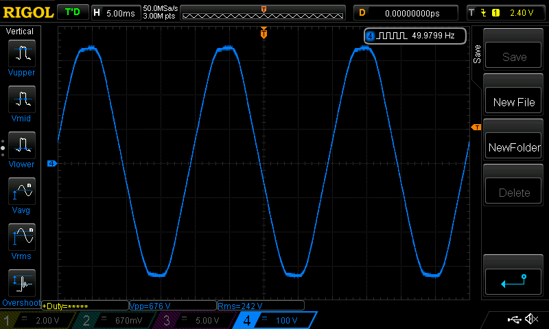
I think there is no value in trying to correct the shape of the AC output voltage.
My view is the AC voltage shape will always be something other than a nice
and clean sinewave. It will always have harmonics of various frequencies and power levels present that produce something like my street power voltage right now.
here is a FFT showing the harmonics of it
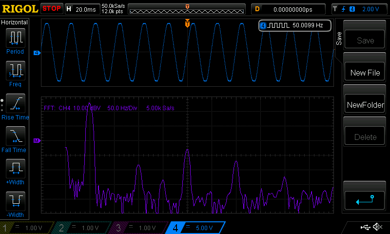
see the strong 250Hz component with -30dbV and the others
at 150 and 350Hz
These probably flatten the peaks of the waveform.
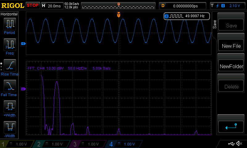
and for comparison, a clean sinewave, again at about 50Hz
To correct a distorted waveform will require well designed voltage sample systems
and closed loop controls. If I was to do this, I would obtain an average error value
(in terms of volts not percentage!) over maybe 20 entire waveforms.
I would maintain a running average of this, which then provides a time averaged error
in volts of the output AC voltage waveform at various angles or waveform positions.
I then use that error to correct, hopefully, the distortion.
But I don't do this in the nanoverter code.
The code samples the AC output voltage, after it is stepped down to 12V, then rectified, then smoothed via a resistor divider. It samples this quantity once
per complete 50Hz cycle. The time of this sample is at a zero crossing of the AC output.
The voltage measured is DC (after step down, rectification and dividing) and so it will be something like 2.5V.
I apply the DC sample of AC output to the PID control loop and correct
the magnitude of the PWM waveform accordingly.
Again, I see no need to correct waveform distortions that are due to loading of the
inverter's output. We try to produce a "clean" sinewave during building of the inverter. This is usually achieved with correct choice of primary inductance, secondary capacitance and toroid build quality.
And then we live with the results when we use the inverter.