Guru
Joined: 02/02/2017
Location: AustraliaPosts: 1404
| Posted: 01:20am 12 Apr 2021 |
Part 40: Current sensors and inverter DC peak current
We are lucky to have access to Aerosharp grid tie inverters
for cheap prices. No matter if they work or not.
The parts inside are what we want.
Every Aerosharp I have dismantled contains 3 LEM brand current sensors.
Usually 2 15 Amp (which can measure +/- 50 Amps actually)
and one 6 Amp sensor (good for +/- 25 Amps)
They are easy to use.
Give it 5V DC supply and all 3 of the sensors will output
2.500V when zero current is flowing through them.
Maximum output is about 0.2V for negative max current and about 4.8V for
positive max current.
Usually the calibration is something like 0.040V/Amp
so with the 2.5V max range, this is 2.5 / 0.040 = 62 Amps
I frequently increase the measure range of these sensors by using a
short shunt to take most of the current and let a small part of it
flow through the sensor. Of course the calibration is wrong, so just
recalibrate it with the shunt in place.
The sensor I used had an extra shunt so it's sensitivity is 0.020V/Amp
so it's max current it can measure is now about 125 Amps
Today I was wondering what the peak current on the DC input of my victim inverter
was when I ran the air compressor.
The first test showed the current way exceeded 125 Amps so I needed extra
shunt.
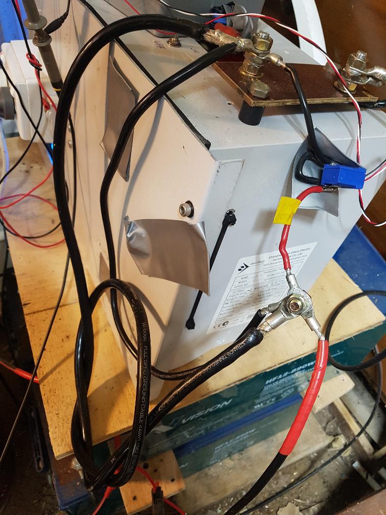
in the below photo you can see the sensor (Blue) and the 3 shunts.
The smallest one is permanently soldered in place, to give 0.020V / Amp
I had to add the other two, to bring the sensitivity down to 0.0092V/ Amp
This means I can measure 2.5V/0.0092 or 270 Amps
Here is the switch on current for the air compressor:
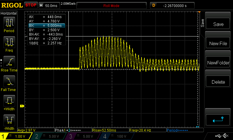
Yellow is DC input current and 1 division = 1V = 108 Amps
Peak current is about 2.26 Volts up from the 2.500V zero level.
This is 245 Amps.
Once the motor settles down (and that only takes about 1/4 of a second)
the current drops to something more reasonable.
An interesting feature of the motor running is the negative current part of
the waveform. It is an AC induction motor after all so it has some reactive power component. This is what reactive power means - there is an exchange of current
between the source (the inverter) and the load (the motor) and this exchange
happens with positive and negative current.
I thought it best to see if I could put a larger load on the inverter.
So I switched on the 2500W 10 Litre hot water urn first, then ran the
compressor.
The Urn takes about 56 Amps DC from the supply. Adding this to 245 Amps is
about 300 Amps. Unfortunately the inverter popped the DC breaker.
OR was that fortunate? Anyway, it survived fine.