Guru
Joined: 02/02/2017
Location: AustraliaPosts: 1432
| Posted: 06:39am 12 Apr 2021 |
Some numbers on the above
245 Amps at about 47V.
If you notice, the waveform is sine but the frequency is 100Hz.
The peak current is at both the positive and the negative peak of the 50Hz
output.
Peak power during motor start is 245 x 47 = 11.5 kW
Wow.
In producing the sine wave output, current flows through (say)
the low side FETS of VS1 which is pulled down to ground and the high side FETS
of VS2 during PWM.
If for instance maximum voltage requires a PWM of width 80% that means
the high side FETS of VS2 are delivering 11.5 kW when only switched on for 80% of the
maximum time. So the current through those FETS is 11.5 / 0.8 = 14.4 kW at waveform peak current.
The powerboard in this inverter is a Madness 6kW totem pole type, with 3 FETS fitted on each of the 4 legs. This means 14.4 kW is passing through 3 FETS on the highside and 3 FETS on the other output low side.
Is this a reasonable result?
14.4 kW at 47 Volts is 306 Amps. There are 3 FETS so each FET handles 103 Amps.
The HY4008 specs give us something called Safe Operation Area
which is showing how much power (or volts x amps) is OK for different pulse widths.
here it is.
The two scales are log scales, you might not be used to these.
I marked a Red dot where 47V and 100 Amps is.
10 ms pulse width is shorter than the pulse widths used in the 20kHz
nanoverter.
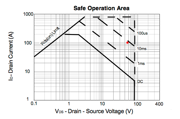
looking at the above I think I am driving the HY4008 about as hard as it's
possible to go without fireworks.
Could anyone here maybe have a look at my argument and confirm or shoot down in flames as required? I am not an E.E.