Guru
Joined: 02/02/2017
Location: AustraliaPosts: 1432
| Posted: 07:51am 17 Jan 2023 |
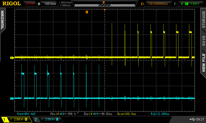
I have improved the nano/picoverter firmware, making the PWM pulsetrain perfectly symmetrical about the zero crossing points.
The results are good. (I don't know why I could not get to this point before.
Maybe I needed a couple of years away from the problem.)
This is the gate drive for V1 and V2 1/2 bridge drives.
In the past there was always a bit extra pulses just after zero crossing.
I have not tested this on a real live inverter yet so there could be a
nasty surprise but I doubt it.
to get this two areas of the code needs to be changed.
First, I needed to make the 1/2 sine wave lookup table finish exactly at Pi radians.
It is now:
void setup()
{
int i;
float t,u;
for(t=0.0,i=0; i < NPWM; i++,t += 3.14159/ (float) (NPWM-1))
{
u = 65535.0 * sin(t); // 1/2 wave sine lookup table, scaled to (16 bits - 1)
l[i] = (int)u;
}
...
Note the small change to the loop.
the other change was to the main interrupt loop, that produces
the inverter's PWM sine wave
//
// 20Khz SPWM, code has only 50uS to run, takes about 10uS
//
ISR(TIMER1_OVF_vect)
{
long c;
if (pcount == 0)
if (v1low == 1) // if first 1/2 wave..
{
TCCR1A = _BV(COM1B1) | _BV(WGM11); // config output compare to suit
}
else
{
TCCR1A = _BV(COM1A1) | _BV(WGM11); // config O.C. to suit
}
c = (l[pcount] * vpwr) >> 16; // scale sine wave by vpwr, 32 bit integer calcs. 16 bit shift fastest of all
if (v1low == 1) // alternate between 2 output compare pins. Get a full 50Hz waveform
{
OCR1B = c; // was c 1/2 out this pin
}
else
{
OCR1A = c; // and then 1/2 out this pin.
}
pcount ++;
if(pcount >= NPWM) // pcount will = NPWM, at each 1/2 wave, at the start
{
pcount = 0; // reset counter
uf=1; // enable one PID control loop execution, in loop()
if (v1low == 1) // if first 1/2 wave..
{
v1low = 0; // toggle to 2nd half wave
sbi(PORTD,7); //DSO pulse
}
else
{
v1low = 1; // toggle to 1st half wave
cbi(PORTD,7);
}
}
The changes were 2 fold.
One was to time the changeover of D9 to D10 PWM at exactly the best time
which is before I write the new PWM width for pulse number 0 for a train of pulses
numbering from 0 to NPWM - 1
The next thing was to do this changeover before I wrote the new PWM width.
The sync pulse out D7 is now 2 PWM pulses early but the pulse train
is now symmetrical, probably to the nearest clock cycle.