Guru
Joined: 02/02/2017
Location: AustraliaPosts: 1432
| Posted: 03:06am 20 Apr 2017 |
Part 5: Experiments with the control loop
First a little review of some things that are important to understand.
(forgive me if you already know what follows, and correct me when I am wrong, please)
The inverter we are all building and hacking uses a closed loop control design
which takes a DC sample of the output AC voltage on the transformer secondary.
This DC voltage (Vfb) may have a lot of 100Hz ripple (if a full bridge rectifier is used, else 50Hz ripple), and unknown amounts of much higher frequency noise mostly coming from the full bridge mosfet switching of the DC supply.
We need to filter Vfb to only let DC into the control loop.
In another post somewhere I showed that the EG8010 IC only samples Vfb during a very short time compared to the 20 ms period of 50Hz output. I think I wrote that Vfb is sampled at the top of one half of the 50Hz output waveform, and the sample window is of the order of 10us. For the rest of the (20milliseconds - 10us) period, Vfb is not sampled.
This means that we need to have Vfb reflect accurately what the output voltage is during that sample time.
Vfb may go all over the place during times when the EG8010 is not sampling it’s value.
The fact that Vfb is sampled synchronously with the output waveform might lead us to simple Vfb filtering designs which work fine on the test bench, usually with purely resistive loads. In the real world the current and voltage can be way out of whack.
This will upset the closed loop control leading to over/under voltage of the output.
So we have to low pass filter Vfb quite heavily to allow for large disturbances from various load types (switching power supplies, SCR controlled lights, motors, flouro lights etc)
I have built a custom inverter prototype using the Arduino (ATMega 328) so as to permit complete control over all aspects of the inverter function. I can use any sort of digital low pass filtering of Vfb I choose. I could do the filtering in hardware but I prefer the flexibility of software.
At last it’s time to look at some results of the closed loop output voltage control.
I use a simple design:
Vfb is fed into one of the ADC ports and is filtered to remove all the high frequency stuff. The 100Hz ripple is quite high, about 0.3V p/p riding on a 2.5V DC signal.
I then sample this voltage about 2,200 or 8,000 times a second and apply some digital filtering to it. Then at the zero Voltage point in the beginning of each 50Hz output, I apply this filtered Vfb value to the PID control loop to calculate the needed PWM duty cycle %.
Digital filtering is done in two ways.
Method 1 is a simple single pole recursive low pass filter - 8,000 Hz sample rate
a = the time constant, in my case a = 0.01.
Initialise ma_ch0 = 0.0
the ADC input is named new_ch0
the filtered output is named ma_ch0
ma_ch0 = ma_ch0 * (1.0 - a) + new_ch0 * a
Method 2is a 4 pole Bessel low pass filter - 2,200 Hz sample rate
It needs a lot more calculations per sample but even on the Arduino it runs at 2,200 Hz
let ch0 = the ADC input value
At the end of these calcs the filtered output is also named ch0
xv[0] = xv[1]; xv[1] = xv[2]; xv[2] = xv[3]; xv[3] = xv[4];
xv[4] = ch0 / 2.259747797e+05;
yv[0] = yv[1]; yv[1] = yv[2]; yv[2] = yv[3]; yv[3] = yv[4];
yv[4] = (xv[0] + xv[4]) + 4 * (xv[1] + xv[3]) + 6 * xv[2]
+ ( -0.7428578687 * yv[0]) + ( 3.1954036268 * yv[1])
+ ( -5.1599230905 * yv[2]) + ( 3.7073065280 * yv[3]);
ch0 = yv[4];
Those ugly coefficients are not easy to calculate and these come from a hugely helpful website at https://www-users.cs.york.ac.uk/~fisher/mkfilter/trad.html
I used an Fc of 0.01 (e.g. 1000 sample rate and 10 Hz Fc) 4 poles, Bessel LP filter
to get these numbers. With a cutoff frequency (Fc) of 0.01, and the 2,200 Hz sample rate, the -3db point is about 22 Hz.
These two methods of LP filtering Vfb behave rather well with the PID control.
Method 1 removes all the 100Hz ripple, as does method 2.
The difference is in the details.
All digital filtering creates a delay in the filtered output compared with the unfiltered source signal. This delay can really screw up the PID control loop if you let it get too long. Imagine if Vfb lagged so much when the control loop increases it’s output so that it starts oscillating..Bad things will happen.
Method 1 gives a smooth result with acceptable delay.
Method 2 gives a smooth result with less of the delay of method 1
which permits a faster responding PID control loop.
I tried Butterworth LP filters but these have a unwanted overshoot on a step input.
This means the filtered signal will follow Vfb as it rises and continue to rise a bit more when Vfb stabilises. Then return back to the correct value. Overshoot is bad when present in the input of a PID loop. So I was forced to use the Bessel filter which has no overshoot with small Fc values.
Time for some pictures.
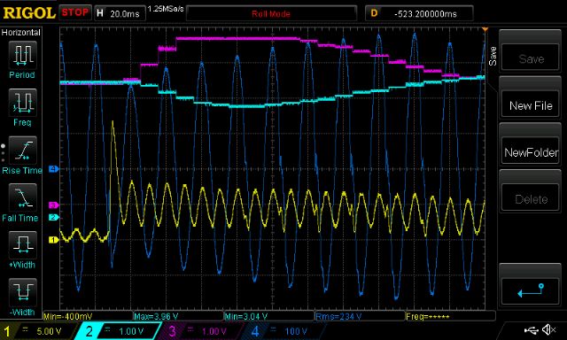
yellow is DC bus current, dark blue is AC output voltage
pink is PWM duty cycle %
light blue is digital filtered Vfb as used by the PID control loop
using method 1
It took about 10 cycles to settle
Notice Vfb minimum is about 4 cycles delayed from AC output.
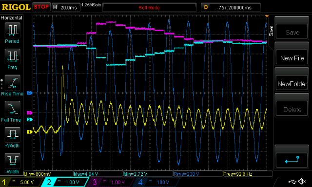
using method 2
It took about 8 cycles to settle.
Vfb minimum is not as delayed, it’s about 3 cycles now.
Looking at the pink trace - PWM duty cycle - you can see that the control loop can assert control much easier with the shorter delay. It needs less time at max PWM to get the output voltage back up. Also I think I am letting some faster changes in Vfb through the filter and into the PID control. (think less attenuation of 10Hz signals compared with method 1)
There is not a huge amount to gain in all this.
I find this sort of investigation a great way to spend some time and it helps me understand what is going on.
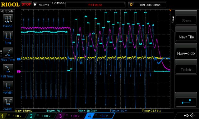
(pink and light blue traces are swapped now.)
This is when it oscillated, due too too much PID gain and too much delay.
I did not damage my inverter when this happened. I use current limited power supplies which lets me get away with murder.
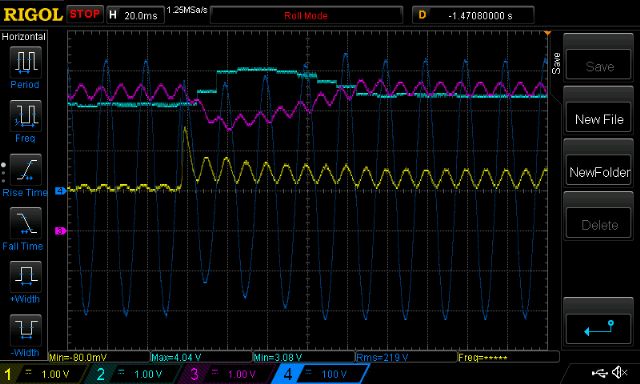
Finally I removed the low pass filtering to see if the control loop will get upset.
It was completely untroubled as you can see.
This is due to Vfb sample time being at the start of the 50Hz cycle every time.
wronger than a phone book full of wrong phone numbers