Guru
Joined: 02/02/2017
Location: AustraliaPosts: 1432
| Posted: 05:39pm 23 Apr 2017 |
Part 6 - transformer resonance and a look at primary winding current
After reading Warpspeed’s post on transformer resonance I thought I wanted to see it.
So, the experiment is set up using
- a sig gen with it’s output configured to drive 50 ohm output
- a 47R resistor, insures with the transformer winding under test.
- one DSO channel looking at sig gen voltage output
- other channel looking at transformer winding voltage
- sweep sine wave from low to high, with a sort of constant amplitude.
Transformer self resonance can be viewed as a LC tank.
Resonant frequency (Hz) = 1/( 2 x pi x sqrt(L.C) )
I use the 1000VA Aerosharp toroid, 25 turns primary. I use the factory wound 240V secondary winding.
I’m lucky to have a BK Precision 879B LCR meter which lets me measure at 100, 1K and 10KHz.
At 100Hz, the primary is 10.6mH with Secondary open, when secondary shorted, the primary becomes 10uH. This 10uH is the leakage inductance. This is not very much at all.
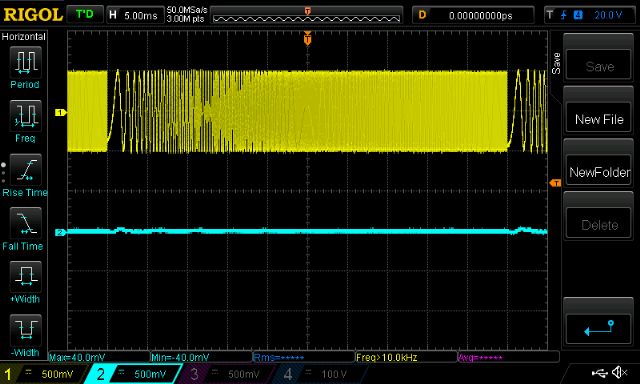
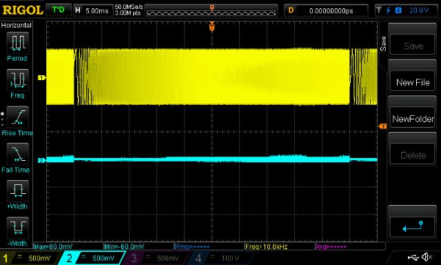
first is 20 - 20KHz sweep, 1v p/p ,2KHz/div horizontal scale
yellow is sig gen output, light blue is primary winding voltage
0.97uF cap across secondary
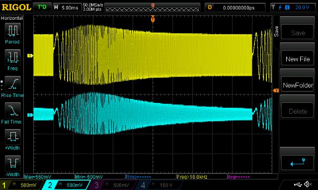
Next shows when secondary is open
Note resonance, peak around 4Khz
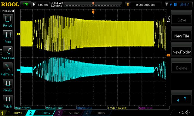
This has the secondary connected to a small 75 VA 240V->25V toroid, into the 240V winding.
Still has the resonance, same peak location.
It’s clear the capacitor does a huge job. Both alter resonance and moderate PWM switch noise.
Now it gets interesting.
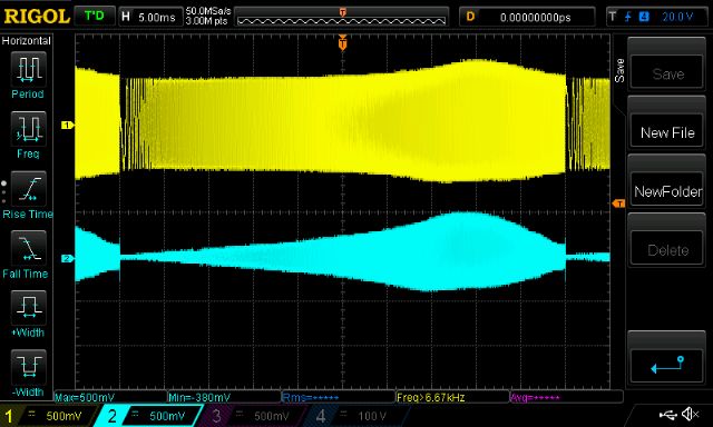
This shows the resonance of my standard test circuit.
The primary has the 50uH choke, the secondary is connected to the 9V Vfb transformer and has a 5uF cap across it.
frequency sweep is now 20Hz - 100KHz
Look at that!
Up around 80KHz this circuit wants to boogie!
And most surprisingly, when I just omit the 50uH choke, the resonance becomes
normal.
So after seeing all this I still see the clear need for a choke (or inductor) in the primary. This is needed to moderate the PWM current peaks.
Time to see the primary winding current
I inserted a short 3mm copper solid wire with a LEM CASR15 current sensor into the primary circuit. This now gives me a view of the current flowing through the mosfet bridge outputs (and primary winding and the choke too. It’s all in series)
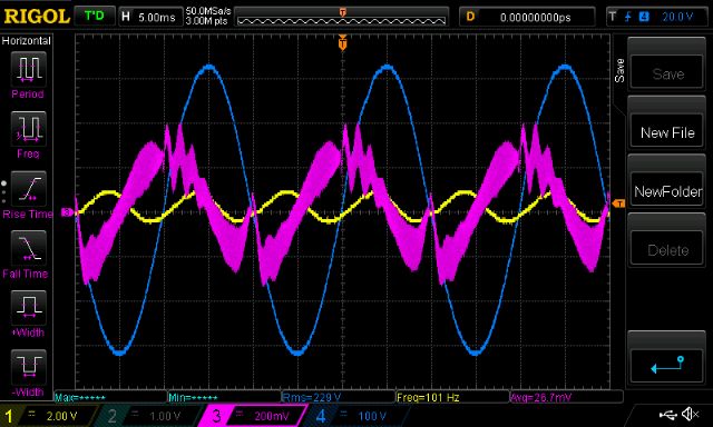
Yellow is DC bus current (about 5A/division)
Blue is AC output
Pink is primary current. Scale is 41.7mV/Amp or about 5A/200mV division
First is idle load. I can see the current leading the AC output, as it should.
Look at the strange disturbances in the current when AC output zero crosses.
Warpspeed may find this of particular interest. Something is happening here. But what it is, I have no idea.
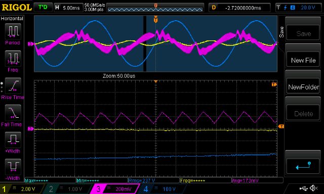
Next is a close-up, which shows the charge up/down of the primary circuit inductance for each of the 20KHz PWM cycles.
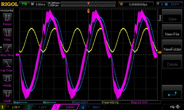
Finally this shows it under my test load, about 170W AC RMS (DC supply 30V)
The primary current is now a lot better looking but still has the zero cross disturbances.
Anyway I hope this helps us get a better grip on what’s happening with our systems.
As usual, please correct me when I am wrong.
wronger than a phone book full of wrong phone numbers