Guru
Joined: 02/02/2017
Location: AustraliaPosts: 1432
| Posted: 03:24am 31 Aug 2017 |
A sneak preview of work in progress:
I have very robust phase lock loop code running on an Arduino Due.
It locks very reliably onto any sync signal from 49Hz to 51Hz
I am feeding it a low voltage sample of my street power.
It locks onto this perfectly well.
The image is a plot of the pll frequency correction factor when tracking the "50Hz" mains.
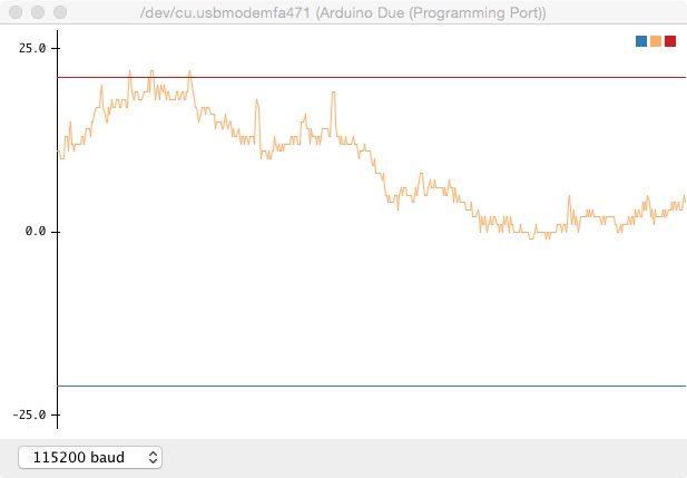
The upper line corresponds to 50.13Hz, the lower to 49.87Hz.
The view shows about 4 minutes of data. See how much the mains power frequency changes.
The abrupt steps of about 1 or 2 units is due to the PLL loop control and it's slightly noisy performance.
I will post more fully on this subject at a later date.
This work is part of an effort to make a small add-on board for the EG8010 to provide a
clock that will ensure PLL locked AC output as generated by the inverter.
If the inverter output is in phase with street power, when the transfer switch operates it might create far less stress in the inverter and household appliances.
wronger than a phone book full of wrong phone numbers