Guru
Joined: 02/02/2017
Location: AustraliaPosts: 1432
| Posted: 07:53pm 16 Aug 2017 |
Part 11: how does the PWM thing work? Just the basic idea..
These inverters we are making and exploring take a DC power source and convert it into
an AC output, fed into the primary winding of a transformer.
See the below circuit, taken from
Tinker's post
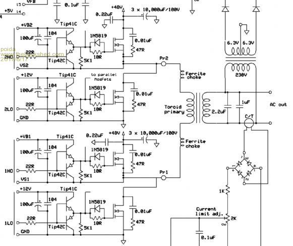
I see the circuit as having 4 switches, named 1LO, 1HO, 2LO and 2HO
When using the EG8010 or EGS002 parts, 1LO and 1HO drive the 50Hz output and 2LO, 2HO drive the 20Khz PWM output.
It's important for my understanding to choose a reference point for all measurements.
I choose DC ground.
IF you put a oscilloscope probe on Pr1 with the probe grounded to DC supply ground you will see
a 50Hz square wave - nearly all the signal will consist of 50Hz square wave, the low 1/2 cycle being close to ground volts and the high 1/2 cycle close to DC bus supply volts.
Put another probe on Pr2 (also this signal is relative to DC supply ground)
This will have a 20KHz square wave running with differing duty cycles depending on where in the 1/2 50Hz cycle you are looking.
(the high frequency PWM signal is a 20KHz square wave with positive duty cycle percentage times varying from sin(0) to sin(90 deg) then back to zero. The inverter power output is controlled by a factor that is multiplied to the sin().
Typically my inverter runs at 70% modulation with zero loads. The modulation factor starts at zero at the start of the 3 second soft-start
then it increases during the 3 seconds to some value that results in the desired AC voltage output as seen by the feedback network)
At steady state running, with the inverter producing it's expected AC output voltage you will see
again a signal at Pr2 that exists primarily at only two values, ground and DC supply.
With a DSO (digital storage oscilloscope) you can quite easily capture portions of the PWM generated for the gate drives.
The transformer primary winding sees the voltage difference between Pr1 and Pr2.
We can easily see what this difference looks like with the oscilloscope
(my DSO has a simulated low pass filter I can apply to a signal and I can perform math functions on 2 signals.)
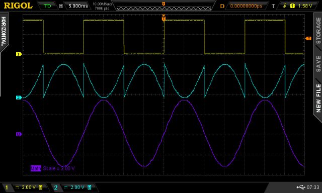
See the following DSO captures
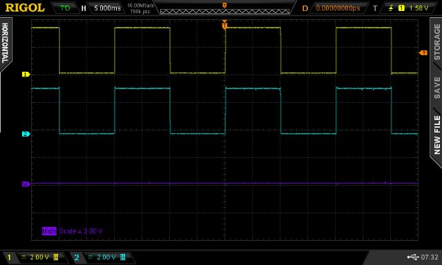
Yellow is the voltage at Pr1
Light Blue is that at Pr2 after passing through a low pass filter.
Purple is (Pr1 - Pr2) i.e. what the transformer gets.
First is where there is zero modulation of the SPWM, leaving the difference = nearly zero.
The primary winding sees differing absolute voltages, changing each 1/2 cycle of the 50 Hz but it sees
nearly zero difference in the two signals.
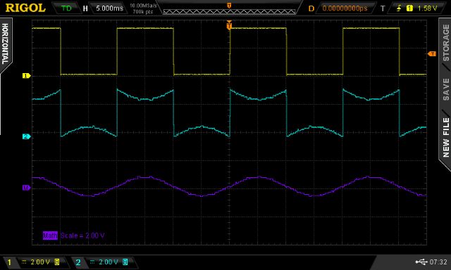
Next I modulate the SPWM to about 10% max, and we see a small sine wave appear on the purple trace.
Subsequent images show increasing modulation of the SPWM.
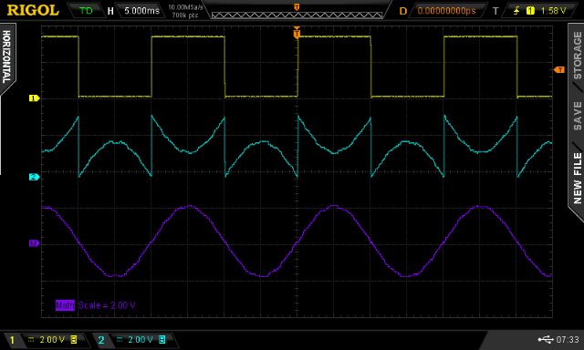
Notice the shape of the high frequency PWM signal (Pr2). See how within one of the 50Hz 1/2 cycles it appears as
a 1/2 of a sine wave? This makes sense since the primary winding sees
the result of (Pr1 - Pr2) which is a sine wave portion going from zero to negative DC bus and back to zero.
The other half of the cycle is a bit strange. Pr1 = Yellow and is at DC bus voltage.
The SPWM is in fact (1 - sin) and so Pr2 starts out at DC bus voltage, reducing down to zero and returning to DC bus.
The primary winding sees the difference of this which is (Pr1 - Pr2) and so thats the positive sine wave half we see in purple.
This is how we can apply an alternating current (going from +DCbus x modulation% to -DCbus x modulation %) to the primary winding.
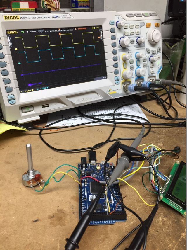
This can easily be done by anyone with a reasonable oscilloscope and an Arduino
I used in this case an Arduino Due (I'm playing with dead-time concepts at the moment)
Here is the code. Attach a potentiometer to A0 to be able to control the modulation %
It includes my very good Bessel 4 pole low pass filter code, which is not used right now.
// include the library code
#include <LiquidCrystal.h>
// initialize the library with the numbers of the interface pins
LiquidCrystal lcd(12, 11, 5, 4, 3, 2);
uint32_t *rp;
const float bessel4[][11] = // Fc,gain,a0,a1,a2,a3
{
{0.0053200, 2635991.5606778641, -0.8537384202 , 3.5510024223 , -5.5404118329 , 3.8431417609 },
{0.0061180, 1524781.5028650849, -0.8337254066 , 3.4878631969 , -5.4739836959 , 3.8198354122 },
{0.0070358, 883513.1860838116, -0.8112892283 , 3.4165503092 , -5.3983852107 , 3.7931060203 },
{0.0080911, 512939.7368203878, -0.7862322979 , 3.3362255664 , -5.3124886713 , 3.7624642100 },
{0.0093048, 298461.1977263077, -0.7583710038 , 3.2460350374 , -5.2150728656 , 3.7273552237 },
{0.0107005, 174105.9270733614, -0.7275473263 , 3.1451347330 , -5.1048310546 , 3.6871517498 },
{0.0123056, 101858.4380555421, -0.6936434579 , 3.0327261291 , -4.9803864405 , 3.6411466885 },
{0.0141514, 59787.5833156785, -0.6565993513 , 2.9081027536 , -4.8403169120 , 3.5885458956 },
{0.0162741, 35224.8633726978, -0.6164331532 , 2.7707099615 , -4.6831925330 , 3.5284615001 },
{0.0187152, 20841.4645647156, -0.5732637347 , 2.6202185372 , -4.5076286708 , 3.4599061679 },
{0.0215225, 12390.4781106740, -0.5273341360 , 2.4566125746 , -4.3123589872 , 3.3817892345 }
};
const uint16_t si[201] = {
0, 129, 257, 386, 515, 643, 772, 900,
1029, 1157, 1285, 1414, 1542, 1670, 1798, 1926,
2053, 2181, 2309, 2436, 2563, 2690, 2817, 2944,
3070, 3196, 3322, 3448, 3574, 3700, 3825, 3950,
4075, 4199, 4323, 4447, 4571, 4694, 4818, 4940,
5063, 5185, 5307, 5429, 5550, 5671, 5791, 5912,
6031, 6151, 6270, 6389, 6507, 6625, 6742, 6859,
6976, 7092, 7208, 7323, 7438, 7553, 7667, 7780,
7893, 8006, 8118, 8229, 8340, 8451, 8561, 8670,
8779, 8887, 8995, 9102, 9209, 9315, 9421, 9526,
9630, 9734, 9837, 9940, 10042, 10143, 10244, 10344,
10444, 10542, 10641, 10738, 10835, 10931, 11027, 11121,
11216, 11309, 11402, 11494, 11585, 11676, 11766, 11855,
11943, 12031, 12118, 12204, 12290, 12375, 12458, 12542,
12624, 12706, 12787, 12867, 12946, 13024, 13102, 13179,
13255, 13330, 13405, 13478, 13551, 13623, 13694, 13764,
13833, 13902, 13970, 14036, 14102, 14167, 14232, 14295,
14357, 14419, 14480, 14539, 14598, 14656, 14713, 14769,
14825, 14879, 14932, 14985, 15036, 15087, 15137, 15186,
15233, 15280, 15326, 15371, 15415, 15458, 15501, 15542,
15582, 15621, 15660, 15697, 15733, 15769, 15803, 15837,
15869, 15901, 15931, 15961, 15989, 16017, 16044, 16069,
16094, 16117, 16140, 16162, 16182, 16202, 16221, 16238,
16255, 16270, 16285, 16299, 16311, 16323, 16333, 16343,
16352, 16359, 16366, 16371, 16376, 16379, 16382, 16383,
16384};
#define NPWM 200
#define PPWM (840000 / (NPWM))
int spa_count,spb[NPWM*2+2],*sp,uf,psc;
int maxpwm,v;
float a0,a1,a2,b1,b2,z1,z2;
int u2,u3;
long pt;
float xv[10],yv[10];
int fc_b4;
float gain,a3;
void setup()
{
uint32_t *t;
int i;
pwm_mod(PPWM);
spa_count=0;
sp = spb;
uf=0;
pwmc_setup();
REG_PWM_CDTY1 = 26250;
ADC->ADC_MR |= 0x80; //set free running mode on ADC
ADC->ADC_CHER = 0xc0+1; //enable ADC on pin A0,A1 and a7
z1=z2=0.0;
/*
volatile unsigned int* SysTickControl = (unsigned int*) 0xE000E010;
*SysTickControl = 0; // disable arduino timer, used by millis() etc.
*/
lcd.begin(16, 2);
// preload Bessel filter coeffs, indexing into above table of values of varying F(cut-off)
i = 10;
gain = bessel4[1];
a0 = bessel4[2];
a1 = bessel4[3];
a2 = bessel4[4];
a3 = bessel4[5];
}
void pwm_mod(long v)
{
int i;
for(i=0; i < NPWM/2; i++)
spb= spb[NPWM-i] = (si[(i * 200) /(NPWM/2)] * v) >> 14;
spb[NPWM/2] = spb[NPWM/2 + 1] = spb[NPWM/2 - 1];
for(i=0; i < NPWM; i++)
spb[i+NPWM]=PPWM - spb;
}
void loop()
{
// work out error, increase or decrease spb[] accordingly
// read analog input, scale and get delta from setpoint, use a bit of PID to drive correction factor
// impliment the soft start, disable/enable output (only during 50Hz zero crossing)
// likely that this code will get interrupted by one or both of the PWM and so we have a situation where
// this code is writing to data that the interrupt routine will be reading.
//
//REG_PIOD_ODSR = 2; REG_PIOD_ODSR = 0; // toggle pin 25
//
//
float r,s,t,f;
int j,k, u;
if(uf==0)
return;
uf=0;
// sample A0, using direct register access
// NO NEED TO CHECK IF ADC result is ready, just read it.
// while((ADC->ADC_ISR & 0x80)==0);
j = ADC->ADC_CDR[7]; // direct ADC conversion read A0
u = ADC->ADC_CDR[6]; // and A1, not used here
s = (float)j / 4087.0;
/*
// 4 pole Bessel LP filter PWM input via noisy potentiometer on A0 line
xv[0] = xv[1]; xv[1] = xv[2]; xv[2] = xv[3]; xv[3] = xv[4];
xv[4] = s / gain;
yv[0] = yv[1]; yv[1] = yv[2]; yv[2] = yv[3]; yv[3] = yv[4];
yv[4] = (xv[0] + xv[4]) + 4 * (xv[1] + xv[3]) + 6 * xv[2]
+ ( a0 * yv[0]) + ( a1 * yv[1])
+ ( a2 * yv[2]) + ( a3 * yv[3]);
s = yv[4];
*/
if (s > 0.999) s = 0.999;
if (s < 0.001) s = 0.001;
v = (int)(s * PPWM);
REG_PIOD_ODSR = 2;
pwm_mod(v);
REG_PIOD_ODSR = 0;
u = 84; // dead time, in uC clocks. arduino due has a 84MHz clock
REG_PWM_DTUPD0 = (u << 16)+u; //can change this on the fly if wanted.
lcd.setCursor(0,0);
lcd.print(s);
lcd.print(" ");
lcd.print(u);
lcd.print(" ");
lcd.print(u3);
lcd.print(" ");
}
void pwmc_setup()
{
//Configure PWM channels 0,1
REG_PIOC_PDR = 0x3FC; //B1111111100, PIO Disable Register
REG_PIOC_ABSR = REG_PIOC_ABSR | 0x3FCu; //B1111111100, Peripheral AB Select Register
pmc_enable_periph_clk(ID_PWM);
REG_PWM_ENA = REG_PWM_SR | 0x000003; //PWM Enable Register | PWM Status Register (activate channels 0,1), was B11111 ie all 5 low
REG_PWM_CMR0 = 0x10000; //Channe0 Mode Register: Dead Time Enable DTE=1, clock divider = 0, use Mclk
REG_PWM_CMR1 = 0x10005; //Channe1 Mode Register: Dead Time Enable DTE=1, clock divider = 5, use Mclk/512
REG_PWM_DT0 = 0x2a002a; //Channe0 Dead Time Register
REG_PWM_DT1 = 0x020002; //Channe1 Dead Time Register
REG_PWM_CPRD0 = PPWM; //Channe0 Period Register 20 kHz
REG_PWM_CPRD1 = 52500; //Channe1 Period Register 50 Hz
NVIC_DisableIRQ(PWM_IRQn); // set up interrupt
NVIC_ClearPendingIRQ(PWM_IRQn);
NVIC_SetPriority(PWM_IRQn, 0);
NVIC_EnableIRQ((IRQn_Type)36); //NVIC_EnableIRQ(PWM_IRQn);
PWM_INTERFACE->PWM_IER1 = 0x0003; //enable interrupt on channel 0
PWM_INTERFACE->PWM_IDR1 = 0x00FF00fc; //enable interrupt on channel 0
// enable 16 pins in port D
REG_PIOD_PER = 0x00ff;
REG_PIOD_OER = 0x00ff;
REG_PIOD_OWER = 0xFFFF;
}
void PWM_Handler(void) // PWM interrupt handler
{
uint32_t ir1;
ir1 = PWM_INTERFACE->PWM_ISR1; // clear interrupt flag
if ((ir1 & 2) == 2) { // runs after each cycle of 50Hz // spa_count=0;
sp = spb + 1;
uf=1;
pt=0;
psc=0;
}
if ((ir1 & 1) == 1) { // runs after each pwm cycle, 20 kHz
REG_PWM_CDTYUPD0 = *sp;
psc++;
sp++;
}
}
Here is Arduino Uno code for the same thing
#define cbi(sfr, bit) (_SFR_BYTE(sfr) &= ~_BV(bit))
#define sbi(sfr, bit) (_SFR_BYTE(sfr) |= _BV(bit))
#define NPWM 200
#define PPWM (160000 / NPWM)
const uint16_t PROGMEM si[201] = {
0, 129, 257, 386, 515, 643, 772, 900,
1029, 1157, 1285, 1414, 1542, 1670, 1798, 1926,
2053, 2181, 2309, 2436, 2563, 2690, 2817, 2944,
3070, 3196, 3322, 3448, 3574, 3700, 3825, 3950,
4075, 4199, 4323, 4447, 4571, 4694, 4818, 4940,
5063, 5185, 5307, 5429, 5550, 5671, 5791, 5912,
6031, 6151, 6270, 6389, 6507, 6625, 6742, 6859,
6976, 7092, 7208, 7323, 7438, 7553, 7667, 7780,
7893, 8006, 8118, 8229, 8340, 8451, 8561, 8670,
8779, 8887, 8995, 9102, 9209, 9315, 9421, 9526,
9630, 9734, 9837, 9940, 10042, 10143, 10244, 10344,
10444, 10542, 10641, 10738, 10835, 10931, 11027, 11121,
11216, 11309, 11402, 11494, 11585, 11676, 11766, 11855,
11943, 12031, 12118, 12204, 12290, 12375, 12458, 12542,
12624, 12706, 12787, 12867, 12946, 13024, 13102, 13179,
13255, 13330, 13405, 13478, 13551, 13623, 13694, 13764,
13833, 13902, 13970, 14036, 14102, 14167, 14232, 14295,
14357, 14419, 14480, 14539, 14598, 14656, 14713, 14769,
14825, 14879, 14932, 14985, 15036, 15087, 15137, 15186,
15233, 15280, 15326, 15371, 15415, 15458, 15501, 15542,
15582, 15621, 15660, 15697, 15733, 15769, 15803, 15837,
15869, 15901, 15931, 15961, 15989, 16017, 16044, 16069,
16094, 16117, 16140, 16162, 16182, 16202, 16221, 16238,
16255, 16270, 16285, 16299, 16311, 16323, 16333, 16343,
16352, 16359, 16366, 16371, 16376, 16379, 16382, 16383,
16384};
uint8_t f50;
uint16_t pcount,uf;
uint16_t l[NPWM+1];
float pwr;
void setup()
{
pwm_mod(0);
noInterrupts();
TCCR2A = _BV(COM2A1) | _BV(COM2B1) ;
TCCR2B = _BV(CS22)| _BV(CS21) | _BV(CS20);
TIMSK2 |= (1 << TOIE2);
pinMode(9, OUTPUT);
TCCR1A = _BV(COM1A1) | _BV(COM1B0) | _BV(COM1B1) | _BV(WGM11);
TCCR1B = _BV(WGM13) | _BV(WGM12) | _BV(CS10);
OCR1A = 10;
ICR1 = PPWM;
TIMSK1 |= (1 << TOIE1);
f50 = 0;
pcount = 0;
uf=0;
interrupts(); // enable all interrupts
TIMSK0 = 0; // except arduino clock
DDRD = B11111111;
pwr=0.0;
}
ISR(TIMER2_OVF_vect)
{// 100 Hz
TCNT2=100;
pcount=0;
f50 = !f50;
TCNT1=0;
uf=1;
}
ISR(TIMER1_OVF_vect)
{//20Khz SPWM
if(pcount == 1)
{
if (f50 == 1)
cbi(PORTD,7);
else
sbi(PORTD,7);
}
if (f50 == 1)
OCR1A = l[pcount];
else
OCR1A = PPWM - l[pcount];
pcount++;
}
void pwm_mod(long v)
{
long i;
long a,c,b;
for(i=0; i < NPWM/2; i++)
{
b = (i * 200)/(NPWM/2);
a = pgm_read_word(&si);
c = (a * v) >> 14;
l= l[NPWM-i] = c;
}
l[NPWM/2 ] = l[NPWM/2 + 1] = l[NPWM/2 -1];
}
void loop()
{
float s;
long v;
float tc=0.1;
if(uf == 1)
{
uf=0;
sbi(PORTD,6);
s = (float)PPWM * (float)analogRead(2)/1024.0;
pwr = (1.0-tc)*pwr + tc * s;
v = (int)pwr;
pwm_mod(v);
cbi(PORTD,6);
}
}
wronger than a phone book full of wrong phone numbers