Guru
Joined: 02/02/2017
Location: AustraliaPosts: 1432
| Posted: 04:20pm 15 Sep 2017 |
Part 14: EG8010 Tfb signal behaviour
After the less than satisfactory performance of the second Aliexpress inverter board, failing after less than 24 hrs when under a load much less than 1000VA I wanted to make things simple.This meant I wanted to remove all chance the EG8010 would stop PWM suddenly.
OZtules has a good understanding of the pitfalls of letting the EG002 board control gate drive IC shutdown, or control PWM output via current feedback.
I wanted to start from the position of zero current feedback limit. I intend to deal with that eventually via a microcontroller.
Oztules uses the Temperature feedback pin to control both simple on/off and over current situations. I wanted to see how Tfb works….
So I set up an EGS002 board on the breadboard with Vfb getting 3.020V to make the EG8010 soft start and remain on. Into Tfb I feed a 5V pulse once every 10 seconds or so or varying widths. I want to see what’s happening.
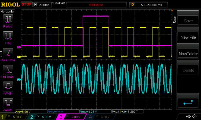
In the following you will see
Purple: Tfb signal
Yellow: 50Hz
light Blue: High side SPWM (sine pulse width modulation)
(I use the “high res” sample function of the DSO, which applies a low pass filter to the inputs. So we see a sort of sine wave here.)
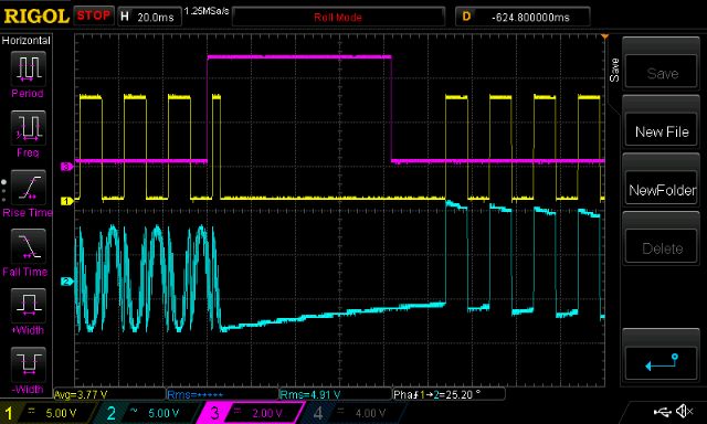
We can see the EG8010 stops the SPWM in mid cycle some random time after Tfb goes high. I saw many examples of this, nearly always the SPWM stops mid cycle.
After Tfb drops below the trigger voltage, SWPM restarts, under soft start control.
The 50Hz does not stop.
There is a minimum Tfb high pulse width that will trigger the stop of SPWM.
It seems to be about 30 - 40ms.
pulse not wide enough:
all that follow have the pulse wide enough.
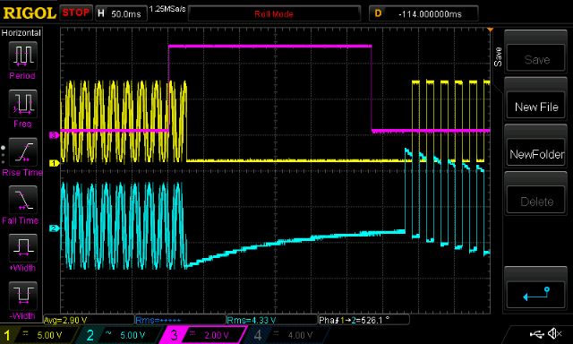
this is what happens if the soft start is still ramping up.
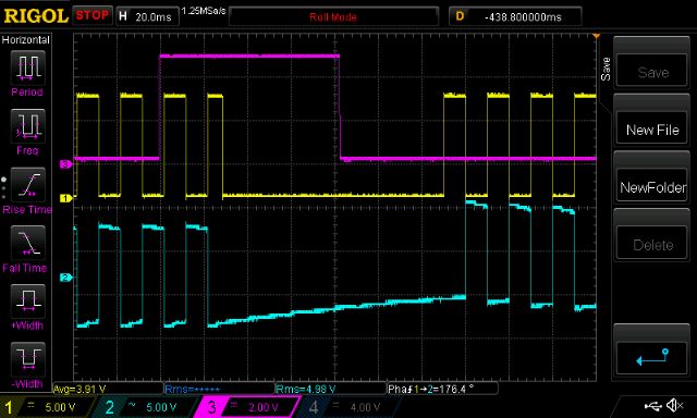
In the following you will see
Purple: Tfb signal
Yellow and light Blue: High and Low side SPWM
I hope this is of some interest to us here.
wronger than a phone book full of wrong phone numbers