Guru
Joined: 02/02/2017
Location: AustraliaPosts: 1432
| Posted: 01:41am 08 Jul 2018 |
Part 23 examining output waveform shape as SPWM varies and as AC output frequency varies
Up until now, we have built and played with inverters that use a constant
SPWM frequency. This is 23.4 kHz when we use the EG8010.
My prototype runs at a nominal 20 kHz.
Also, our inverters output AC at 50 Hz.
I modified the Arduino code to permit any SPWM frequency from about 5kHz up to 40kHz,
controlled by a potentiometer. I can change the SPWM frequency while the inverter is running under load, to examine the AC output waveform or primary winding current.
I also run code modified to allow the control of the AC output frequency, varying
anywhere from 40Hz to 100Hz.
I wanted to see how the SPWM filtering went as the frequency was varied.
I expected to find some frequency or other which made the inverter go bananas,
causing bad things to occur.
I have two versions of inverter program running on the Arduino.
Version 1 is just like that which runs on the EG8010, it produces a 50Hz fundamental output on one channel and
a 20kHz SPWM output on the other channel.
Version 2 instead makes a nominal 20kHz sine wave PWM on both channels, one being 180 degrees out of phase to the other. When you feed these two outputs into a transformer, you get the difference which is of course a sine wave.
This version has a soft start and a soft stop.
I use version 2 in these experiments since it requires twice as many PWM switch events per second compared with version 1, and so it is feeding 2x as much high frequency energy into the transformer/choke/filter system as well.
The test conditions are:
27.4 V DC supply
1.95uF filter cap on the secondary
1500VA Aerosharp toriod (0.7 VRMS /turn) with 18 turns on primary, 335 turns on secondary
46uH E core ferrite choke with an air gap (non saturating at my test currents)
no load on secondary.
— No mosfets were harmed in the production of these videos —
First I vary the PWM frequency, from about 5kHz to 40 kHz via a potentiometer by hand.
The output AC freq = 50Hz, PWM freq is shown bottom right, in yellow. The primary current is light blue.
Notice you can hear the PWM when it comes within audible ranges.
video
From the video I can say there are no PWM frequencies that lead to catastrophic resonances
It just works fine. We see less and less variation in primary current during PWM switching
as the frequency goes up and this is to be expected since the freq is rising so the inductor has less
energy to store each time.
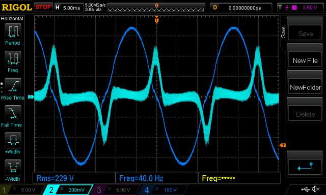
Next I vary the AC output frequency by hand via the pot.
The fat trace is primary current (“light blue” but the camera has no exposure control in movie mode..)
video 2
At around 40 Hz things are clearly unhappy. Is it due to the parallel LC resonance of the toriod?
Idle current has risen to 1.0A, 3x more than normal and you can hear that things are not running well.
40 Hz with 1.95uF cap
I change the filter cap from 1.95uF to 6.45uF and try again.
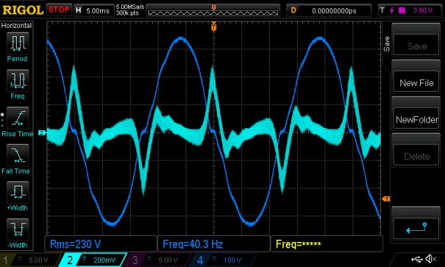
No improvement or change in this bad high current condition.
It seems it's not effected by parallel LC resonance frequency - it's due to something else.
Idle currents
40Hz (1.95uF) 1.06A (6.45uf) 1.00A
50Hz 0.37A 0.51A
60Hz 0.33A 0.52A
80Hz 0.29A 0.64A
Notes:
Using faster PWM means more mosfet switching losses but we can use a smaller choke.
Increased switching losses are small when I double the PWM frequency so it's quite feasible to use 40kHz PWM to permit a smaller or more easier to build choke.
The bad running at 40Hz may be due to my PWM programming, maybe some detail I have overlooked in the Arduino code makes a problem that goes very bad at low AC output frequencies. I doubt it.
But more likely I think I have no idea how transformers and PWM full bridges behave so there is most likely some effect happening at 40Hz which will become clear once I study the basics of electronics further. I put the DC clamp meter on the primary, maybe at this freq, the PWM is producing increasing DC current in the primary winding. If so this would be a bad thing. But no, the current remains around 0.3 to 0.4A throughout the 40 - 80 Hz range.
I want also to note that I find great value in the education that a simple Aurduino micro controller,combined with a short program, $100 of parts, free parts extracted from a dead grid tie inverter and some time can give.
The setup:
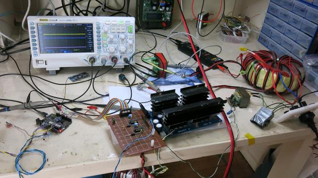
wronger than a phone book full of wrong phone numbers