Guru
Joined: 02/02/2017
Location: AustraliaPosts: 1432
| Posted: 02:34am 21 Oct 2018 |
Part 24: thermal thoughts
We are making (and breaking) inverters built using HY4008 mosfets.
Typically we have 3 or more, up to 6 of these paralleled on each
of the 4 legs of the full bridge.
I was interested in how well heat is removed from the chip, via the TO-247 package
and into the heatsink.
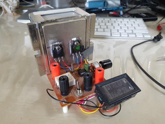
I have built and abused, Royally, a very handy DC constant current load.
It senses drain to source current and drives the fet gates to maintain a desired DC current. 2 mosfets share the same gate drive. It works fine and I love it.
It uses NEC K3304 mosfets I pulled out of a dead plasma TV.
These are in a TO-3P package, similar to the TO-247.
This toy handles 120W continuous and 1 minute pulses over 150W with ease.
Under load the 2 K3304 fets dissipate all the heat and transfer it to the heatsink.
I have found on numerous occasions the heatsink is hotter than the front of the
TO-3P package, to my calibrated finger. Much hotter.
This is good, it shows the heat is being conducted well, away from the chip and to the back of the package.
I was wondering one day how our favourite MOSFET goes, in this situation.
So I made a test DC load, able to drive 2 mosfets with independent gate drives
that maintain the desired current.
The test load:
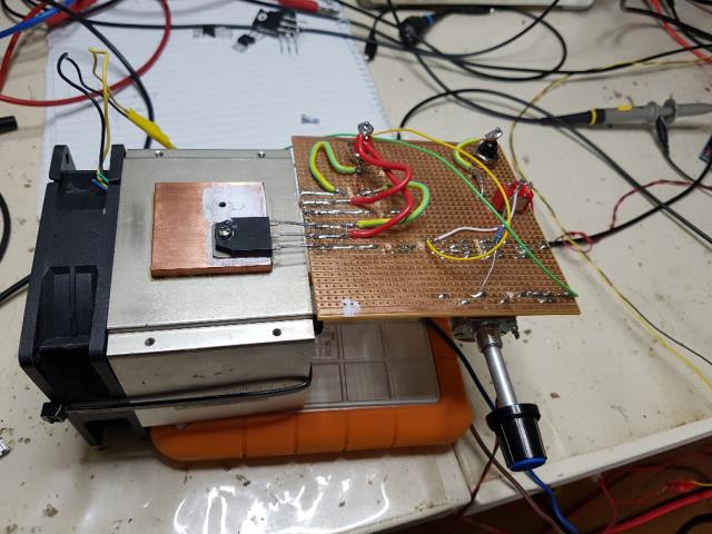
First, I used one gate drive for 2 mosfets but always one or the other fet would heat up and take all the load. The Gate threshold voltage is variable with these devices.
SO I built 2 current sense, gate drive circuits, to prevent one fet taking all the current.
Anyway, the Hy4008 in TO-247 package is in my experience poor at conducting heat to the heatsink. You can easily feel a hotspot appear on the front of the case, then the heat sink warms a little, then the hotspot gets hotter and hotter. Always the heatsink stayed quite a bit cooler than the front of the case.
I swapped the Hy4008 for the NEC K3304.
Immedately I could feel the heatsink get hotter BEFORE you could feel heat on the front of the case. The difference was surprising. I tested this at 30V and 2 amps in both cases.
I also have a bag of TO-220 packaged HY4008. I tried the same and got the same result
of a much hotter front of the package compared with the heatsink.
So what's all this got to do with the price of fish?
Hooyi Semiconductor provide specs for their chips and one I found interesting is
max continuous current
This is 200 A at 25Cj (at the chip junction) and
153 A at 100Cj
and max power
397W at 25Cj and
199W at 100Cj
In testing I have blown these HY4008 with as little as 5A, when attached to a heatsink. Easy, just supply 30V at 5A and that's 150W.
I did not power it for long, just 1 second, the time needed to twist the power supply current limit knob.
The TO-220 packaged HY4008 are less capable of conducting heat and break easier.
I didn't get to 5 amps before it failed.
I started it cold, with a good heat sink compound under it.
less than a second ramping it to 5 amps kills the fet with a 30V supply.
It dies well before 150W and these are rated at 173W at 100Cj.
The junction must heat up very quickly and not conduct heat to the case.
The de-rating curve shows 100W max at 130C.
I suspect Hooyi have designed these chips in a way that they have poor heat conduction from the chip junction to the case.
My views on using these in our inverters:
they are cheap.
they work.
I have no idea how they continue to work.
Do not use them unless they are fully switched ON or OFF.
When used in the saturation area, they are very weak devices.
DO NOT let them get hot.
** MOSFETS were harmed in the preparation of this article.
wronger than a phone book full of wrong phone numbers