Guru
Joined: 02/02/2017
Location: AustraliaPosts: 1432
| Posted: 01:39am 06 Nov 2018 |
Gaspo:
I'm not sure how you are getting these signals.
Just to make sure we are both on the same page we need to be both using the
same type of Arduino and looking at the same pin's outputs.
I am using the 2x sine code, loaded into an Arduino Uno.
The code requires two timers to be present, and we use the output compare
function to drive pins 9 and 10 from TIMER1.
We need access to OC1A and OC1B for this function.
If you are using an Arduino that has a different chip than an ATMEGA 328p
then we probably will see different results.
All the codes posted by me require an ATMEG 328p uC and it's simple and cheap to get them from ebay at $10 each when you buy a "UNO board".
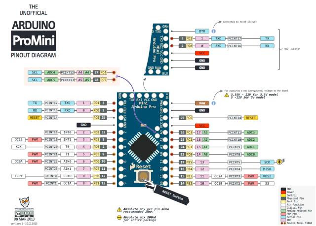
I see from a prior post that you are using a "pro-mini"
This uses the ATMega 328.
here is the pinout:

I see pins 9 and 10 are connected to OC1A and OC1B.
This is good.
Make sure you feed it 5V so it runs at 16Mhz just like a Uno.
The video I posted for Tinker shows outputs on 3 pins.
Pins 9 and 10 are Yellow and light Blue. (OC1A and OC1B)
The Purple trace is pin 7.
This pulse is the result of the following:
..
if(pcount >= NPWM)
{
pcount = 0;
sbi(PORTD,7); // give a sync pulse for DSO, alligned with start of 50Hz
cbi(PORTD,7);
}
..
wronger than a phone book full of wrong phone numbers