Regular Member
Joined: 08/03/2019
Location: United KingdomPosts: 64
| Posted: 06:14pm 13 Mar 2019 |
Poida, brilliant work with the scope. It's amazing to see the waveforms with 500MHz sample rate as they really do show up everything that is otherwise missed qyuite easily. I'm still scratching my head reading through some of it.. brilliant stuff.
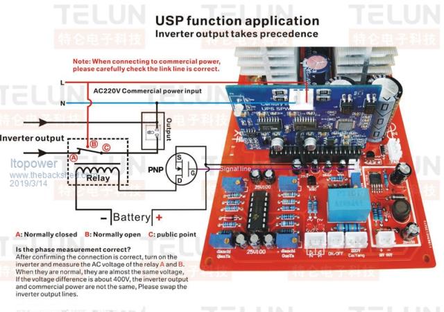
I read a while back in various posts about a UPS style version board and found it on Aliexpress, wondering if two units given a common stabilised input frequency if they would syncronise enough together to allow the two transformer outputs to be coupled. Small variations in the frequency lock may well create some degree of oscillation ?

This would then allow an incremental build out of a larger inverter capacity.. this would also avoid them from actually being used as a UPS just a syncronised group of boards..
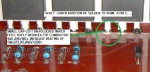
This is my inverter board that turned up today.... in need of some more solder on some of the drain and source legs.....

The effect of this small difference to FET leg position and heating effect would be quite interesting to know, although not entirely sure how this could be measured effectively. Maybe a comparison between two FET's as I noticed your picture with the scope leads the drain and source are in a similar low solder situation ?