
|
|
Forum Index : Solar : Sodium Ion Install
| Author | Message | ||||
Dinosaur Guru Joined: 12/08/2011 Location: AustraliaPosts: 357 |
Hi All Don't know how many on this forum have used Sodium Ion prismatic cells, but I have just spent a couple of months perfecting it for my use. Purchased 4 x 230AH cells for $230 delivered to Hervey Bay. I hope the comments below will help someone else b4 they purchase. Cells: Veken 72173207-230AH. I don't believe they are the latest technology available. They were meant to be shipped at 3% capacity, but were actually at 30%. The terminals are female M6 at 125mm Centres, which is an improvement on the stud plates that break off on the Lithium Cells. I put Brass studs into them and then used Brass Nuts & Washers to connect bars and Inverter Cables. The cells are fractionally larger and heavier than Lithium Cells. 207H x 175D x 72W and weighs 5.1kg. My control Board is mounted directly onto the +/- studs. It uses only copper bars. No flying lead cables other than the Solar coming in and Loads out. Voltages. The quoted capacity is 230AH, but this is from 1.5V to 3.95V per Cell. So for a 12V system = 6v to 15.8V. I am using this in a Camper, so 6V is of no use to me. Similarly, my Renogy Inverter considers anything over 15.375V an error. Accordingly in my software I have simply reset 100% to 15.4V and 0% to 11V. That means I lose any capacity over 15.4V and below 11V. I can go to the limit of say 15.75 as long as I don't try to use the Inverter. However, a trial of my 1000W Microwave for 5 min, dropped the battery to 80%, and I am happy with that. My Brass Monkey fridge has some settings that can be adjusted, otherwise the high voltage will be considered a Low 24V and it will shutdown. Balancing: Even though the cells measure to spec at 0.1mOhm, when connected to the other cells they do not settle and balance themselves over a week. Typically they stay about 40mV out of balance. I installed a 10A Transformer Active balancer. Control: Using 2 x ADS1115 boards that equates to 4 Cell Voltages, 1 Differential Solar V and 1 differential Current shunt V. I do not measure Cell Temperature. As my Solar is below 40A, I am using 1 x 60A SSR that is pwm . The software chases MPPT and controls the charging current. All of this happen on a Rpi Zero 2W with a 10" lcd. A cpu cooling fan is relay controlled to switch on above 60 C. No RTC is fitted. The critical info is transmitted to the Cab via Wifi hotspot onto my GPS screen. Planning a Camping trip in the next few weeks, so that will be the final test. Hope this was informative for the Forum members. Regards Regards Hervey Bay Qld. |
||||
| poida Guru Joined: 02/02/2017 Location: AustraliaPosts: 1478 |
I am interested in your monitoring system. Rpi zero and what else you use? custom or home brew software? wronger than a phone book full of wrong phone numbers |
||||
| Dinosaur Guru Joined: 12/08/2011 Location: AustraliaPosts: 357 |
Hi All The software in the Rpi is written in FreeBasic and uses an external Library for pwm & i2c called Periphery. The only downside of the library, is that you can't adjust by .1% increments, only 1%. As usual for me the most difficult is the conversion of the .h to .bi include files. However, AI has done a great job of that. If anyone is interested I can post those. Other than that most time was taken in the charging logic. When to just thump the current in and when to start controlling it. Stopping the hunting when you think you have achieved a Target Voltage. I do a full scan of all I/O every 15 sec's update the screen and then nothing in between, which keeps the Rpi cool as well. The charging method is then re-evaluated and changes made. No GUI, only a Terminal screen with all the description & info I am interested in. Will try to post that pic. Changing text colour to a bright magenta (color 11) for the info that changes every cycle. In the software I record why changes were made and where, then translate that into a single number on the screen. A single Keystroke will save 100 samples of a2d for each of the 6 channels into .csv files. The Rpi drives BC107 transistors that drive: 1: JayCar 60A SSR with 5vdc pwm.(Chinese brands failed on Current capacity) I put a homemade L channel heatsink under the SSR.It hasn't got warm yet. 2: Small CPU Fan Relay with 12vdc which only comes on when it is hot as all of this is deep inside the Ute with a Canopy on top and other camping stuff blocking air flow. On the pic you can just see it removed but on the left. 3: Blue Xeon Alarm Light so I can be alerted when driving that something has gone wrong. Happened once with my LiPo4 Cells when I left the Inverter on to long. 4: Each O/P is connected back to an I/P and is used to confirm the status of each O/P. I2C: 2 x ADS1115 a2d converters on i2c.Precision resistor dividers, however I calibrate the conversion to an accuracy of about 3mV for the Cells. SolarV is less demanding and it has an accuracy of about 40mV. Current shunt is good for 34mA All of these are of course calibrated with charging Off. I actually bought a Voltage standard to confirm which of my Multimeters was accurate. It is worth noting that I have had a number of board failures when using the miniature version of this board, but the larger board (Gravity) has had none. On each channel you need to throw away the first 10 readings to allow settling and prevent cross contamination from other channels. The channels are multiplexed. When you then graph the .csv files in Excel the values are remarke-ably stable. The counts sit within 1 count and slowly goes down over many minutes as the Rpi etc consumes power. 1 x 12v to 5vdc converter, it has a switch in the Canopy for easy night time shutdown. 1 x Modified shunt. I only measure Solar Current as total load of lights and Fridge are known. The Inverter bypasses the shunt as it sometimes takes 180A. Simply cutting bars out of a 250A Shunt made it a 50A accurate shunt. pwm: The Current measured and SolarV are used to calculate Wattage pumped into the battery. Depending on the SOC of the battery I pre-assign allowed Currents and thus pwm %. Below a snippet of code that achieves that. ''========Block of code to decide direction========= when Battery is NOT full yet. If .Direction < 0 Then '' Last Direction was DOWN If .Delta_Watts < 0 Then '' AND the Watts went DOWN If A2D.Err_I < 0 Then '' AND NOT @ Max current yet .Action = 16 '' then allow a direction change. .Direction = +1 Else '' otherwise if OVER Max Current .Action = 17 '' Keep going DOWN .Direction = -1 EndIf Else '' IF the Watts went UP whilst adj DOWN .Action = 18 '' keep going DOWN .Direction = -1 '' untill within Current Range. EndIf Else ''-----------------------------------------'' IF Last Direction was UP If .Delta_Watts < 0 Then '' AND the Watts went DOWN .Action = 19 '' then change direction. .Direction = -1 '' regardless of Err_I Else '' IF the watts went UP If A2D.Err_I < 0 Then '' AND under Max current .Action = 20 '' then keep going UP. .Direction = +1 Else .Action = 21 '' otherwise if OVER Max Current .Direction = -1 '' go DOWN EndIf EndIf EndIf ''====================================================== Hope you get a better picture from this. Regards Hervey Bay Qld. |
||||
| Dinosaur Guru Joined: 12/08/2011 Location: AustraliaPosts: 357 |
Hi All Picture of running screen. Screen1.pdf Regards Hervey Bay Qld. |
||||
| Dinosaur Guru Joined: 12/08/2011 Location: AustraliaPosts: 357 |
Hi All Unable to load Picture of Board mounted on the Cells. Converted .png to 50% size Printed to .pdf Tried .zip None will work. Regards Hervey Bay Qld. |
||||
Revlac Guru Joined: 31/12/2016 Location: AustraliaPosts: 1281 |
Hi, thanks for posting the info on the Sodium Ion cells, and your personal review and usage, very helpful.  I don't have any Sodium Ion batteries but are interested in the starting batteries...details some other time, Also good of you to stick your neck out and try new stuff for your self and see the results, so much better to learn this way. There are still many who have a fear of trying new or different batteries and just carry on with the old tried and tested mentality and the rants about batteries that they never tried and know nothing about, and never learn anything if they don't get up off there arse and try, We learn so much more from hands on experience trying these things than hype posted by Sellers and other parties.   Not trying to start a fire but user experience is more valuable than sales pitch Not trying to start a fire but user experience is more valuable than sales pitch I know my old Taiwanese inverters cant use much of the capacity (in fact very little) of this type of battery chemistry but our home brew inverters can do much better with the wide voltage range of these if designed to. The PDF image loads but is far too big to be displayed on the forum, resize to 1024x768 if you tried and it didn't work there must be something else going on. Cheers Aaron Off The Grid |
||||
| Dinosaur Guru Joined: 12/08/2011 Location: AustraliaPosts: 357 |
Hi All Thanks Revlac for the suggestion. Converting a png to pdf makes the image almost unreadable. However, zipping the png file worked well, so hopefully you can download it and unzip it. The 6mm clear Acrylic lid with fan is removed for the photo, but is just visible on the right. The Renogy 2000 Watt Inverter at the lower end of the photo. The visible green light is the balancer mounted directly on the cells. The whole thing is secured onto Concreters Ply, that slides into the ute out of the way. Inside my Canopy I have a small lid that opens to the ute base and gives me access to the Isolator and Inverter switch if I need it. Board1png.zip Regards Hervey Bay Qld. |
||||
| Revlac Guru Joined: 31/12/2016 Location: AustraliaPosts: 1281 |
That's nice neat looking setup. 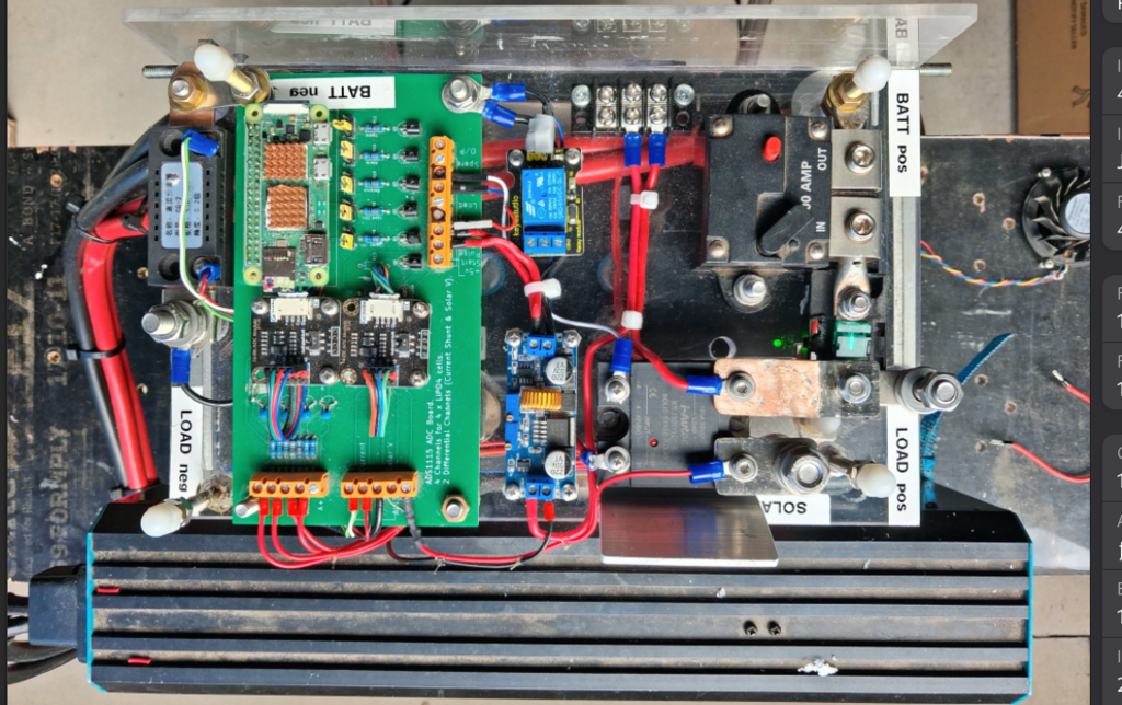 Ok uploaded. The bootlace ferrules work well in those terminal blocks. Edited 2026-05-11 19:23 by Revlac Cheers Aaron Off The Grid |
||||
| Dinosaur Guru Joined: 12/08/2011 Location: AustraliaPosts: 357 |
Hi All I was reluctant to use those ferrules for many years as I saw wires easily pulled out. However once I learned NOT to use them on solid core wire AND pick the right size ferrules, it swayed me. They are also so much easier to push into the kind of terminals that have a clip keeping the hole closed until you push something solid into them. Did you notice how I used the lugs into the Isolator ? Also the 40A fuse just to the right of the green led. The hardest thing to get in Hervey Bay were the Nylon Dome nuts that keep the lid on. Didn't want something metallic accidentally sliding across it and shorting terminals out. Regards Hervey Bay Qld. |
||||
Chopperp Guru Joined: 03/01/2018 Location: AustraliaPosts: 1126 |
I had someone say this to me a number of years ago. I said "You did crimp them first, didn't you?". "No" was the reply with a blank look. Using the appropriate sized ferrules and then crimping with the appropriate crimper is very important. I do have the correct crimping tool but for size...well whatever I can find near enough at the time... Brian ChopperP |
||||
| Revlac Guru Joined: 31/12/2016 Location: AustraliaPosts: 1281 |
I had to look up that style of breaker in the photo, yes you did well there, good use of terminals. Yes the nylon dome nuts are a good addition it reminds me I should do something like that to some parts on my battery system, especially the main battery isolator I have...a little bit of 3D printing will fix that one day. Cheers Aaron Off The Grid |
||||
| Dinosaur Guru Joined: 12/08/2011 Location: AustraliaPosts: 357 |
Hi All Just a follow up. The max charge voltage per cell is 3.95v x 4 = 15.8 Battery Voltage. As I said before, the Renogy 2000W Inverter is good for 16V, however it throws an error around 15.375. I charged the battery to 15.6 and turned on the inverter. Within about 15 Sec's I turned on the Microwave (100 + Amps). By the time the inverter decided to do something about the High Voltage I was already below 15.375V. So, I can set the 100% mark at 15.6v keeping away from the Limit of 15.8. Another win, so installing it in the Ute late next week after which I can test the Fridge as well. Regards Hervey Bay Qld. |
||||
| The Back Shed's forum code is written, and hosted, in Australia. | © JAQ Software 2026 |
