
|
|
Forum Index : Solar : Simple PV diversion unit
| Author | Message | ||||
| davef Guru Joined: 14/05/2006 Location: New ZealandPosts: 499 |
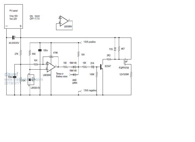 While trying to get a SMPS boost unit to feed power into a 230V hot water tank element I had a play with a 12V 300 Watt DC rated element and this simple analogue diversion unit. The idea was proposed by SolarMike, that of using a capacitor to transfer energy from the panel while keeping the panel near its Vmp. I tried to supply the LM358 directly from the PV input but couldn't get it to fire up cleanly so went to a constant 13V5 supply. The discrete AND gate is so that other inputs can control the Hi-side PFET, ie temperature, the state of the main 13V5 battery, etc. Haven't optimised the switching points. |
||||
| hotwater Senior Member Joined: 29/08/2017 Location: United StatesPosts: 120 |
Sounds simple enough, but you can get into real trouble since the frequency is not fixed. It can quickly turn into a high frequency linear oscillator and overheat the FET due to inadequate drive. P-FET should be avoided due to cost and poorer performance. 7.5V is not a lot of drive to get full saturation. |
||||
| davef Guru Joined: 14/05/2006 Location: New ZealandPosts: 499 |
As this PFET has a +/-20V V(BR)GSS the zener is probably redundant. Point taken about drive I will investigate further. I was reading through this which suggested the P-FETs were better, but I think better as in easier to implement not best from a rDS point of view! I don't understand the statement. The repetition frequency changes with the amount of PV power with the ON-time being fixed. |
||||
| Solar Mike Guru Joined: 08/02/2015 Location: New ZealandPosts: 1123 |
Dave, the cct could be modified to use a N channel with low side switching and have better drive for faster on off times. The emitter followers can be small signal transistors. Your voltage sensing switch circuit will act as a low frequency oscillator when the sense voltage drops below the panels set mppt reference value and at low light levels will switch on and off at a variable frequency determined by the sensing hysteresis. If you use a mosfet with 5-10mR on resistance then very little power will be wasted. Unless there is a good reason to use a high side switch of course... 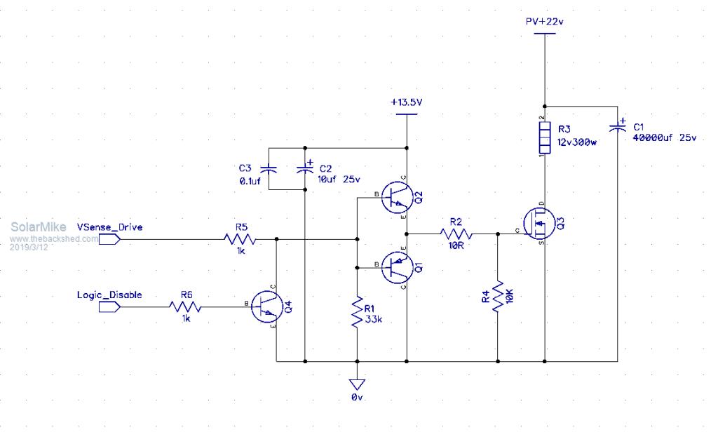 Cheers Mike |
||||
| davef Guru Joined: 14/05/2006 Location: New ZealandPosts: 499 |
Hi Mike, Thanks for the circuit. In the document I linked they discussed the boot-strapping approach for N-FETs. I will try modifying it to use a N-FET. |
||||
| Warpspeed Guru Joined: 09/08/2007 Location: AustraliaPosts: 4406 |
I have had a great deal of success with those e-bay two dollar Chinese postage stamp sized power supplies. They come to life at around 30v dc input, (if very lightly loaded) and are probably safe up to about 400v dc input. They are very well regulated too, and the fully isolated output can be useful for generating negative dc voltages. They are probably the "guts" used in the now very common switched mode type wall plug packs. Cheers, �Tony. |
||||
| davef Guru Joined: 14/05/2006 Location: New ZealandPosts: 499 |
Could you provide a link then I will look on Aliexpress? Thanks, Dave |
||||
| hotwater Senior Member Joined: 29/08/2017 Location: United StatesPosts: 120 |
I use those ans the safest you can get them to start with modification is about 41V. Just search 12V 1.25A They come in a little aluminum case for about $1.50US. I think people shouldn't be told that P-FET exist till they are a seasoned designer. And then they would say......Why did you bother telling me that? In the last 30 years I don't remember ever seeing a P-FET in a commercial piece of equipment. |
||||
| Warpspeed Guru Joined: 09/08/2007 Location: AustraliaPosts: 4406 |
This is typical of the smaller type, rated at around five watts, and various dc output voltages from 3v to 18v. If run with zero load, or just a few tens of mA load they generally start up around 30v to 35v dc input. https://www.ebay.com.au/itm/5W-AC-DC-12V-450mA-Power-Supply-Buck-Converter-Step-Down-Module-AU-NEW/302088719078?ssPageNa me=STRK%3AMEBIDX%3AIT&_trksid=p2060353.m1438.l2649 There are larger higher power versions, but the smaller ones seem to start up a bit more readily at very low input voltages. I believe these things are made by the million in China, available from many different vendors, and are the "guts" out of the familiar dc wall packs that sell for ten times the price. Cheers, �Tony. |
||||
| davef Guru Joined: 14/05/2006 Location: New ZealandPosts: 499 |
Tony, thanks for the link and especially the operating hints. hotwater, actually we had about 20 different models of mobile radios that used hi-side P-FET switches. It is rather difficult to DC control a LDMOS RF device where you can not put anything in source connection. I only used what I knew and now I know for this application a N-FET makes more sense. Now I will have to review several others places where I use P-FETs as an N-FET might be a better choice there too. Cheers, Dave |
||||
| hotwater Senior Member Joined: 29/08/2017 Location: United StatesPosts: 120 |
It may not seem obvious. For a self powered unit, the most dangerous time is when the array is producing less than 10W. You wouldn't think you could destroy a FET with that. Having under voltage lock out is a must. |
||||
| davef Guru Joined: 14/05/2006 Location: New ZealandPosts: 499 |
The under-voltage lock out is part of the design, ie the LM358 comparator. I have some STM STP80N70F4 with about 8mOhm RDS(on) which is about 1/2 of the FQPF47P06. |
||||
LadyN Guru Joined: 26/01/2019 Location: United StatesPosts: 408 |
I would like to understand this further. I understand that at 10W point, the Vgs is nearing Vth and hence in the linear region where Rds is pretty high. HOWEVER, how much is Ids in this situation, because (Ids ** 2) * Rds is the power dissipation and at that high Rds, I do expect Ids to be pretty low when sourced from a 10W source? It's obvious to me I'm missing something but I would like to know what |
||||
| hotwater Senior Member Joined: 29/08/2017 Location: United StatesPosts: 120 |
Chances are for a self powered unit it will go into oscillation driving the FET in a linear region. This is the reason a true functioning low voltage drop out is needed. The TL494 does have a low voltage drop out, but it was designed almost half a century ago when there were just transistors. I do all my testing at early dawn. That is where all the design problems show up. Full sun is a piece of cake. |
||||
| LadyN Guru Joined: 26/01/2019 Location: United StatesPosts: 408 |
Ah, I see where the disparity is - you're talking about a self powered unit while Dave is powering the opamp externally from a stable regulator PSU. Besides using gate drivers with built in LVO, I believe a LVO can be designed using two TL431s to provide some hysterisis? Still, my question above stand: how much is Ids in this situation, because (Ids ** 2) * Rds is the power dissipation - which is I assume, what kills the FET and at that high Rds, I do expect Ids to be pretty low when sourced from a 10W source? |
||||
